
Turn on suggestions
Auto-suggest helps you quickly narrow down your search results by suggesting possible matches as you type.
Showing results for
Please log in to access translation
Turn on suggestions
Auto-suggest helps you quickly narrow down your search results by suggesting possible matches as you type.
Showing results for
Community Tip - Have a PTC product question you need answered fast? Chances are someone has asked it before. Learn about the community search. X
- Community
- Creo+ and Creo Parametric
- Analysis
- Re: Structural simulation of pressurized tube - co...
Translate the entire conversation x
Please log in to access translation
Options
- Subscribe to RSS Feed
- Mark Topic as New
- Mark Topic as Read
- Float this Topic for Current User
- Bookmark
- Subscribe
- Mute
- Printer Friendly Page
Structural simulation of pressurized tube - constraints?
Feb 16, 2023
07:17 AM
- Mark as New
- Bookmark
- Subscribe
- Mute
- Subscribe to RSS Feed
- Permalink
- Notify Moderator
Please log in to access translation
Feb 16, 2023
07:17 AM
Structural simulation of pressurized tube - constraints?
Hi,
I would like to simulate in Creo 4 the mechanical stress and deformation of a thin-walled tube under an internal gas pressure.
I am having problems finding the best constraints for the results that I want.
Ideally, I would like to constrain the tube around its central axis. So that the resulting deformation of the tube wall is axi-symmetric around the tube central axis.
But I can't find a way to constrain the tube around its axis.
The only contraints that lead to some results (although not the ones I want) is to use the (flat) starting surface of the tube.
If I use the 'Planar' constraint (or Z = fixed, X and Y free) I get stresses that seem acceptable, but the deformation is wrong and not axi-symmetrical.
If I fix the surface in X,Y and Z, I get a result, but as expected, the deformation is 'weird'.
If I constrain as a 'Pin', that does not work.


Solved! Go to Solution.
ACCEPTED SOLUTION
Accepted Solutions
Feb 16, 2023
09:52 AM
- Mark as New
- Bookmark
- Subscribe
- Mute
- Subscribe to RSS Feed
- Permalink
- Notify Moderator
Please log in to access translation
Feb 16, 2023
09:52 AM
I think I have found a way to achieve what I had in mind.
First, create a new coordinate system, but make sure it is a cylindrical one. Put the CS on the tube axis, with 2 datumplanes as references.
Define displacement for the end surface of the tube, where you use the cylindrical CS as reference. Fix Z and Theta. Keep R free.
This solves into a nice axi-symmetric deformation, and the VM stress matches my manual calculation.
To check the diameter deformation, I have to use X or Y deformation. Using 'Magnitude' takes the shortening of the tube into account, which I don't need.


10 REPLIES 10
Feb 16, 2023
08:17 AM
- Mark as New
- Bookmark
- Subscribe
- Mute
- Subscribe to RSS Feed
- Permalink
- Notify Moderator
Please log in to access translation
Feb 16, 2023
08:17 AM
This article outlines the principles used to approach constraints of this type of problem. See the 3-2-1 method in particular. You should take advantage of the axisymmetric symmetry of the pipe as well when possible.
https://www.digitalengineering247.com/article/free-floating-fea-models/
========================================
Involute Development, LLC
Consulting Engineers
Specialists in Creo Parametric
Involute Development, LLC
Consulting Engineers
Specialists in Creo Parametric
Feb 16, 2023
09:43 AM
- Mark as New
- Bookmark
- Subscribe
- Mute
- Subscribe to RSS Feed
- Permalink
- Notify Moderator
Please log in to access translation
Feb 16, 2023
09:43 AM
Thank you!
That is an interesting article, as it clearly pin-points the problem I am facing too: to create a decent 'fixed world' constraint so that the calculated results display what I want to see.
The 3-2-1 method is perfect to constrain the model if you are only interested in stresses. My problem is that I am also interested in deformation. And to show deformation, I want to use a reference point (the tubes axis) where there is no geometry (no material). So I can not place a node there.
I think I found a way. See my other post.
Feb 16, 2023
09:52 AM
- Mark as New
- Bookmark
- Subscribe
- Mute
- Subscribe to RSS Feed
- Permalink
- Notify Moderator
Please log in to access translation
Feb 16, 2023
09:52 AM
I think I have found a way to achieve what I had in mind.
First, create a new coordinate system, but make sure it is a cylindrical one. Put the CS on the tube axis, with 2 datumplanes as references.
Define displacement for the end surface of the tube, where you use the cylindrical CS as reference. Fix Z and Theta. Keep R free.
This solves into a nice axi-symmetric deformation, and the VM stress matches my manual calculation.
To check the diameter deformation, I have to use X or Y deformation. Using 'Magnitude' takes the shortening of the tube into account, which I don't need.
Feb 16, 2023
09:57 AM
- Mark as New
- Bookmark
- Subscribe
- Mute
- Subscribe to RSS Feed
- Permalink
- Notify Moderator
Please log in to access translation
Feb 16, 2023
09:57 AM
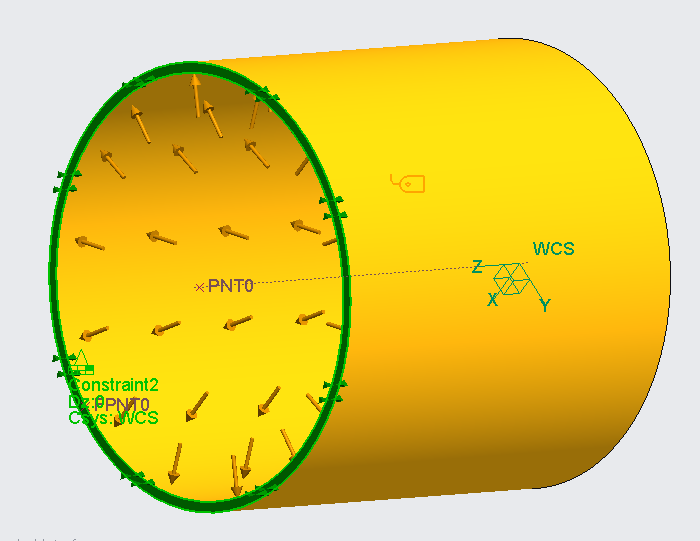
I also tried by using the inner tube wall surface as displacement reference. Same cylindrical CS as reference, also R free, Z and Theta fixed.
The result was not as accurate as the above because the fixed Z prevented the shortening of the tube. Showing like this:


Feb 17, 2023
04:03 AM
- Mark as New
- Bookmark
- Subscribe
- Mute
- Subscribe to RSS Feed
- Permalink
- Notify Moderator
Please log in to access translation
Feb 17, 2023
04:15 AM
- Mark as New
- Bookmark
- Subscribe
- Mute
- Subscribe to RSS Feed
- Permalink
- Notify Moderator
Please log in to access translation
Feb 17, 2023
04:15 AM
Thank you for providing the example. Unfortunately, I do not have the required Simulate license.

Feb 17, 2023
05:32 AM
- Mark as New
- Bookmark
- Subscribe
- Mute
- Subscribe to RSS Feed
- Permalink
- Notify Moderator
Please log in to access translation
Feb 17, 2023
06:41 AM
- Mark as New
- Bookmark
- Subscribe
- Mute
- Subscribe to RSS Feed
- Permalink
- Notify Moderator
Please log in to access translation
Feb 17, 2023
06:41 AM
This example I could open.
I modified the geometry and material to match those in my example and the results (stress and displacement) are the same in both models.
I guess the key is to use a cylindrical coordinate system.
Thank you so much for your input!
Feb 21, 2023
08:17 AM
- Mark as New
- Bookmark
- Subscribe
- Mute
- Subscribe to RSS Feed
- Permalink
- Notify Moderator
Please log in to access translation
Feb 21, 2023
08:17 AM
I might have started with quarter symmetry like this, using a cartesian coordinate system.
But yes, since you want displacements relative to the central axis, the cylindrical coordinate system is the best answer.
Also, full models of things that have symmetry will not have totally correct symmetry in results due to small numerical issues and possible non-symmetric meshing/elements. Symmetry is not just used to reduce the model size and speed up solving time as it can also give the most correct result.
A limitation of cylindrical based constraints is that you can only get reaction forces for constraints defined by the cartesian world coordinate system (WCS)

Feb 21, 2023
10:38 AM
- Mark as New
- Bookmark
- Subscribe
- Mute
- Subscribe to RSS Feed
- Permalink
- Notify Moderator
Please log in to access translation
Feb 21, 2023
10:38 AM
Yes, I should make more use of symmetry. I am currently working on another simulation where the part geometry, constraints and loads are perfectly symmetric. Yet, the stresses on the left and right side of the part are different.
Probably, like you said, due to numerical issues and or meshing.
Thanks for your input!
Announcements


Top Tags
