
Turn on suggestions
Auto-suggest helps you quickly narrow down your search results by suggesting possible matches as you type.
Showing results for
Please log in to access translation
Turn on suggestions
Auto-suggest helps you quickly narrow down your search results by suggesting possible matches as you type.
Showing results for
Community Tip - Visit the PTCooler (the community lounge) to get to know your fellow community members and check out some of Dale's Friday Humor posts! X
- Community
- Creo (Previous to May 2018)
- Creo Modeling Questions
- Re: how to unfold the pipe
Translate the entire conversation x
Please log in to access translation
Options
- Subscribe to RSS Feed
- Mark Topic as New
- Mark Topic as Read
- Float this Topic for Current User
- Bookmark
- Subscribe
- Mute
- Printer Friendly Page
how to unfold the pipe
Jul 10, 2014
06:37 AM
- Mark as New
- Bookmark
- Subscribe
- Mute
- Subscribe to RSS Feed
- Permalink
- Notify Moderator
Please log in to access translation
Jul 10, 2014
06:37 AM
how to unfold the pipe
i have tried to unfold the pipe using rip with sketch but its not working it always shows a failure msg. can anyone suggest a way
Solved! Go to Solution.
ACCEPTED SOLUTION
Accepted Solutions
Jul 11, 2014
04:46 PM
- Mark as New
- Bookmark
- Subscribe
- Mute
- Subscribe to RSS Feed
- Permalink
- Notify Moderator
Please log in to access translation
Jul 11, 2014
04:46 PM
Sagar,
You need to use correct orientation of part in view to get correct value.
You can create new view in part or in drawing change the orientaion of view using Geometry references in View properties.
28 REPLIES 28
Jul 10, 2014
04:32 PM
- Mark as New
- Bookmark
- Subscribe
- Mute
- Subscribe to RSS Feed
- Permalink
- Notify Moderator
Please log in to access translation
Jul 10, 2014
04:32 PM
Tubes are tricky in sheetmetal. There are any number of reasons it doesn't want to unfold.
If you can attach the file a post, we can probably help with more specific answers.
Jul 11, 2014
02:22 AM
- Mark as New
- Bookmark
- Subscribe
- Mute
- Subscribe to RSS Feed
- Permalink
- Notify Moderator
Please log in to access translation
Jul 11, 2014
02:22 AM
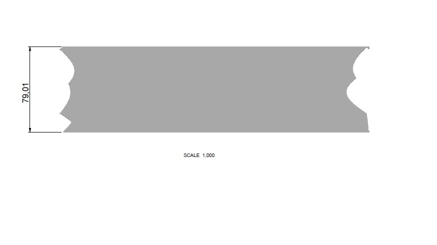
sir i have unfolded the tube but now what problem i am facing is in the sheetmetal the opened tubed width is 80.225 mm but when i take it to drawing its width becomes 79.1 its creating a problem in wrapping this profile around the pipe for notching. 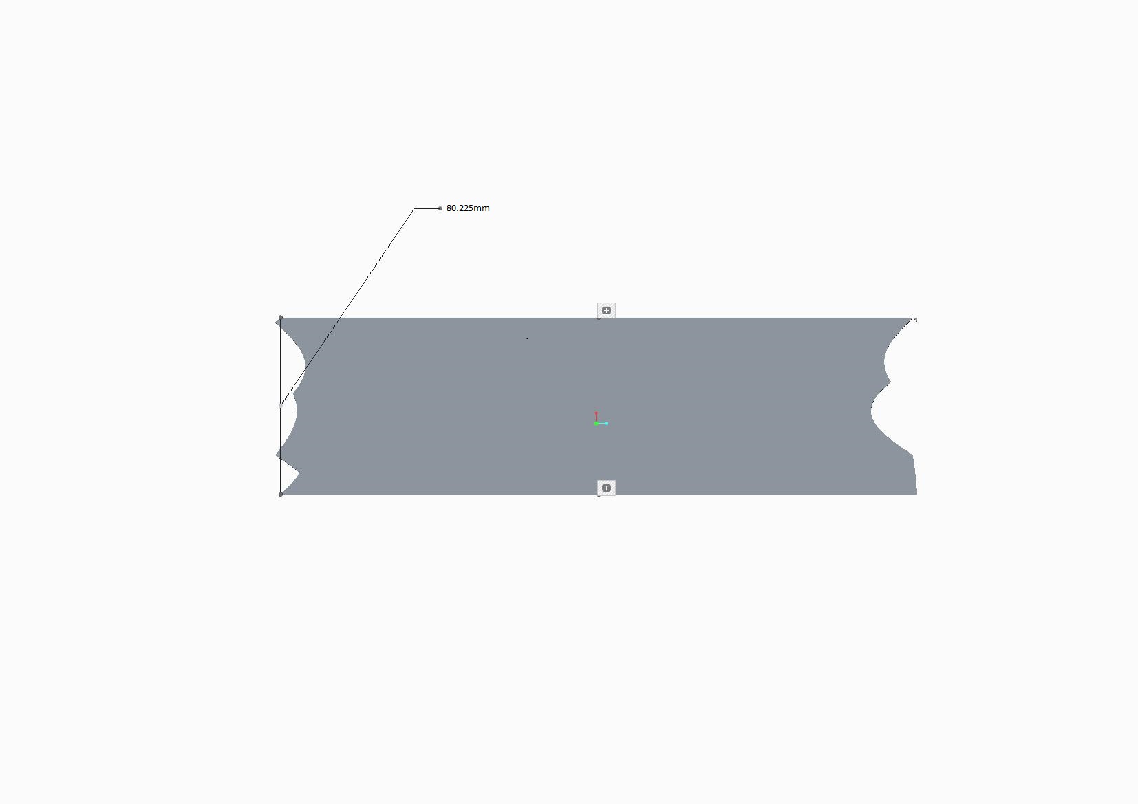
Jul 11, 2014
02:55 AM
- Mark as New
- Bookmark
- Subscribe
- Mute
- Subscribe to RSS Feed
- Permalink
- Notify Moderator
Please log in to access translation
Jul 11, 2014
02:55 AM
It appears that the y-factor is being applied twice.
Jul 11, 2014
03:08 AM
- Mark as New
- Bookmark
- Subscribe
- Mute
- Subscribe to RSS Feed
- Permalink
- Notify Moderator
Please log in to access translation
Jul 11, 2014
03:08 AM
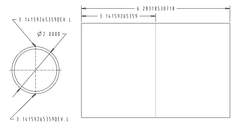
sir actulal circumference of the tube should be (pi*26.9) that is 84.4mm but how it has been reduced. is there a way to get the desired circumference
Jul 11, 2014
03:16 AM
- Mark as New
- Bookmark
- Subscribe
- Mute
- Subscribe to RSS Feed
- Permalink
- Notify Moderator
Please log in to access translation
Jul 11, 2014
03:16 AM
https://www.dropbox.com/s/a9186jgewpo3rwf/sheet1.prt.1
sir this is the link to the unfolded pipe .prt file
Jul 11, 2014
11:39 AM
- Mark as New
- Bookmark
- Subscribe
- Mute
- Subscribe to RSS Feed
- Permalink
- Notify Moderator
Please log in to access translation
Jul 11, 2014
11:39 AM
I will look at the model. The difference between the model unfold and the drawing unfold is troubling.
Sheetmetal does not use the outer circumference for calculations. Sheetmetal uses either a K-factor or Y-factor in order to account for stretch and crush of the metal when it is formed. It is a balance between the inside radius and the outside radius. This is more prominent for sharp bends and you can set the value for items such as tubes which use more gentle radii than bends.
Jul 11, 2014
11:50 AM
- Mark as New
- Bookmark
- Subscribe
- Mute
- Subscribe to RSS Feed
- Permalink
- Notify Moderator
Please log in to access translation
Jul 11, 2014
11:50 AM
sir thanks for looking into the issue but is there a way i can get the outer circumference of the tube as 84.4mm.
i have tried increasing the y-factor but i dont have an idea in what proportion its increasing.
Jul 11, 2014
12:02 PM
- Mark as New
- Bookmark
- Subscribe
- Mute
- Subscribe to RSS Feed
- Permalink
- Notify Moderator
Please log in to access translation
Jul 11, 2014
12:02 PM
Try both 0 and 1. I think 0 maintains the ID circumference and 1 maintains the OD circumference.
Jul 11, 2014
12:16 PM
- Mark as New
- Bookmark
- Subscribe
- Mute
- Subscribe to RSS Feed
- Permalink
- Notify Moderator
Please log in to access translation
Jul 11, 2014
12:16 PM
with 1 i am getting 82.225mm instead of 84.4mm and with 0 its 78.22mm .
Jul 11, 2014
02:41 PM
- Mark as New
- Bookmark
- Subscribe
- Mute
- Subscribe to RSS Feed
- Permalink
- Notify Moderator
Please log in to access translation
Jul 11, 2014
02:41 PM
I am sorry but your model file is an educational version. I cannot open these files.
I will try some experiments with my version to see what the values return.
Jul 11, 2014
03:02 PM
- Mark as New
- Bookmark
- Subscribe
- Mute
- Subscribe to RSS Feed
- Permalink
- Notify Moderator
Please log in to access translation
Jul 11, 2014
03:02 PM
Sagar,
As Antonius mentioned, you can get the desired results by changing the K & Y factor. In your part file you need to set K-Factor as 1, this will give you the required diemnsion 84.51 (pi*26.9).
Yes, by default K-factor is grayed out to change the value and to enable that you need to set Sheetmetal parameter SMT_UPDATE_BEND_ALLOW_INFO as no.
Jul 11, 2014
03:17 PM
- Mark as New
- Bookmark
- Subscribe
- Mute
- Subscribe to RSS Feed
- Permalink
- Notify Moderator
Please log in to access translation
Jul 11, 2014
03:17 PM
Thanks for weighing in, Mahesh.
I confirmed this in a simple model.
I typically prefer K-Factor. I don't know what Y-factor does at the limits.
Jul 11, 2014
03:20 PM
- Mark as New
- Bookmark
- Subscribe
- Mute
- Subscribe to RSS Feed
- Permalink
- Notify Moderator
Please log in to access translation
Jul 11, 2014
03:20 PM
sir is this a new method i am not able to get what you were trying to explain here
Jul 11, 2014
03:18 PM
- Mark as New
- Bookmark
- Subscribe
- Mute
- Subscribe to RSS Feed
- Permalink
- Notify Moderator
Please log in to access translation
Jul 11, 2014
03:18 PM
i have tried the procedure you have described but the dimension its giving is 80.225mm
Jul 11, 2014
03:26 PM
- Mark as New
- Bookmark
- Subscribe
- Mute
- Subscribe to RSS Feed
- Permalink
- Notify Moderator
Please log in to access translation
Jul 11, 2014
03:26 PM
Ok, try below steps:
1. Open that part, File Prepare > Model Properties > Change the parameters > change the value of SMT_UPDATE_BEND_ALLOW_INFO as no > Ok
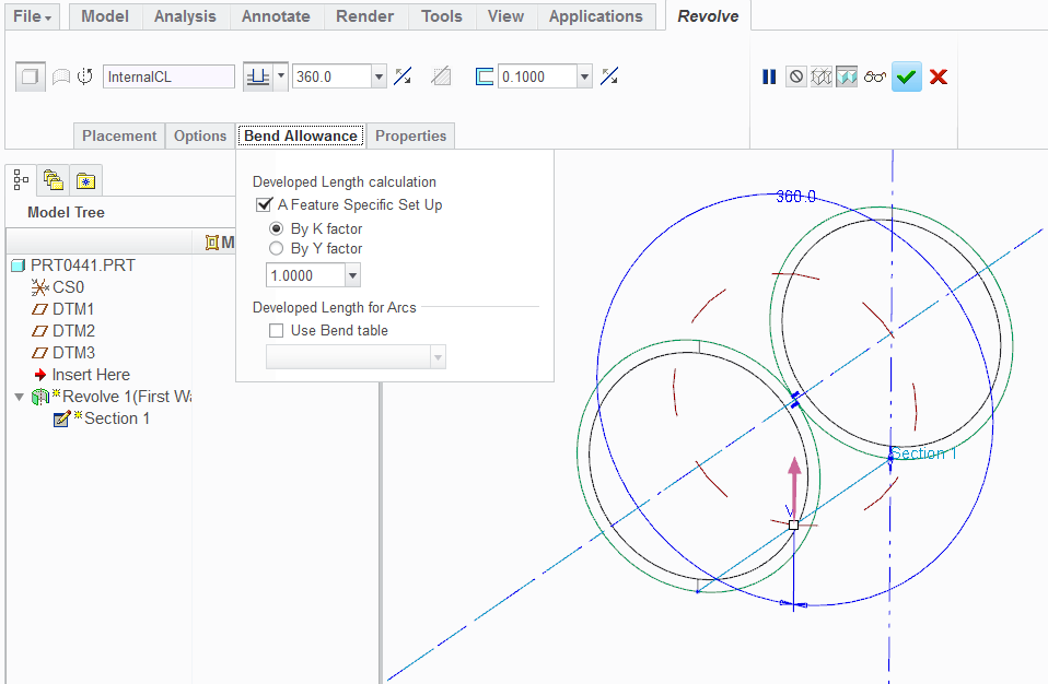
2. Nowith in same Model Properties Change Bend Allowance > Select K Factor > Enter value as 1 > Regenerate > Close
Jul 11, 2014
03:29 PM
- Mark as New
- Bookmark
- Subscribe
- Mute
- Subscribe to RSS Feed
- Permalink
- Notify Moderator
Please log in to access translation
Jul 11, 2014
03:29 PM
mahesh sir i have tried that out its not working
Jul 11, 2014
03:33 PM
- Mark as New
- Bookmark
- Subscribe
- Mute
- Subscribe to RSS Feed
- Permalink
- Notify Moderator
Please log in to access translation
Jul 11, 2014
03:33 PM
Will you explain where you are getting incorrect value, in drawing or in part?
If in drawing, which orientation you are using for view?
Jul 11, 2014
03:36 PM
- Mark as New
- Bookmark
- Subscribe
- Mute
- Subscribe to RSS Feed
- Permalink
- Notify Moderator
Please log in to access translation
Jul 11, 2014
03:36 PM
mahesh sir i am getting wrong value in sheet metal itself
Jul 11, 2014
03:44 PM
- Mark as New
- Bookmark
- Subscribe
- Mute
- Subscribe to RSS Feed
- Permalink
- Notify Moderator
Please log in to access translation
Jul 11, 2014
03:55 PM
- Mark as New
- Bookmark
- Subscribe
- Mute
- Subscribe to RSS Feed
- Permalink
- Notify Moderator
Please log in to access translation
Jul 11, 2014
03:55 PM
Very nice to know. Thank you Mahesh.
Jul 11, 2014
03:32 PM
- Mark as New
- Bookmark
- Subscribe
- Mute
- Subscribe to RSS Feed
- Permalink
- Notify Moderator
Please log in to access translation
Jul 11, 2014
03:32 PM
Maybe Mahesh can open the education model you provided and have a look at what may be wrong.
Are you using Creo 2.0?
The method I used to make the pipe is a first feature as a Revolve.
This is where the K-Value is set.
Jul 11, 2014
03:35 PM
- Mark as New
- Bookmark
- Subscribe
- Mute
- Subscribe to RSS Feed
- Permalink
- Notify Moderator
Please log in to access translation
Jul 11, 2014
03:35 PM
sir pipes which i am trying to unfold are chassis pipes that are already made in AFX extension i have converted then into sheet metal by shell command and then i have done sketch rip and then unbend it.
Jul 11, 2014
03:39 PM
- Mark as New
- Bookmark
- Subscribe
- Mute
- Subscribe to RSS Feed
- Permalink
- Notify Moderator
Please log in to access translation
Jul 11, 2014
03:39 PM
Antonius,
The part file uploaded by Sagar is a converted sheetmetal part. Initially part was created using extrude and later on converted to sheetmetal. I will upload a movie file for step by step, hopefully that will help Sagar.
Jul 11, 2014
03:46 PM
- Mark as New
- Bookmark
- Subscribe
- Mute
- Subscribe to RSS Feed
- Permalink
- Notify Moderator
Please log in to access translation
Jul 11, 2014
03:46 PM
mahesh sir that would be really helpfull
Jul 11, 2014
04:02 PM
- Mark as New
- Bookmark
- Subscribe
- Mute
- Subscribe to RSS Feed
- Permalink
- Notify Moderator
Please log in to access translation
Jul 11, 2014
04:02 PM
sir with the help of video i was able to get the circumference as 84.255 thanks for your support but when i am taking the sheet in drawing the tube stays attached to it . i only want the sheet.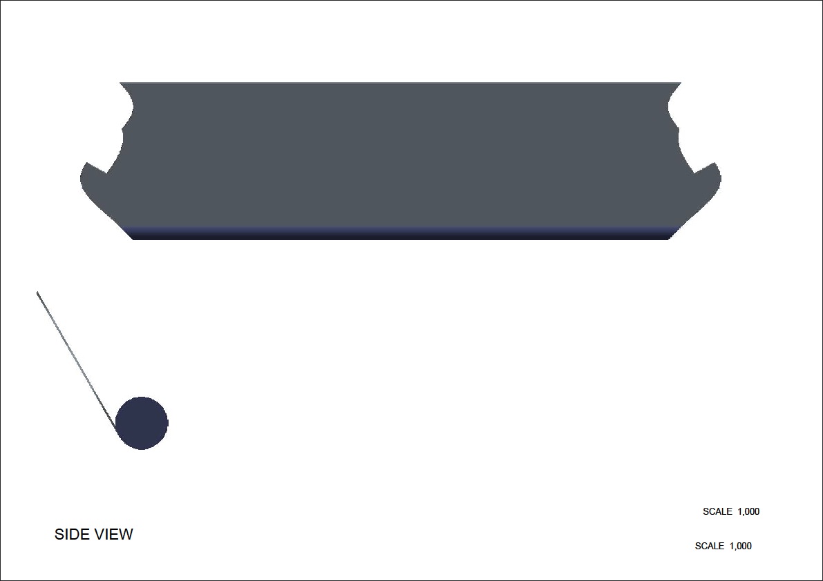
Jul 11, 2014
04:13 PM
- Mark as New
- Bookmark
- Subscribe
- Mute
- Subscribe to RSS Feed
- Permalink
- Notify Moderator
Please log in to access translation
Jul 11, 2014
04:13 PM
Sagar,
Tube is surface geometry, to hide that in drawing:
1. In Drawing, File > Prepare > Drawing properties > Change Drawing options
2. Set drawing option ignore_model_layer_status as no > Add/Change > Apply > Close
3. review > Update Sheets.
Jul 11, 2014
04:26 PM
- Mark as New
- Bookmark
- Subscribe
- Mute
- Subscribe to RSS Feed
- Permalink
- Notify Moderator
Please log in to access translation
Jul 11, 2014
04:26 PM
thankyou sir tube has gone but still the dimension in drawing are not right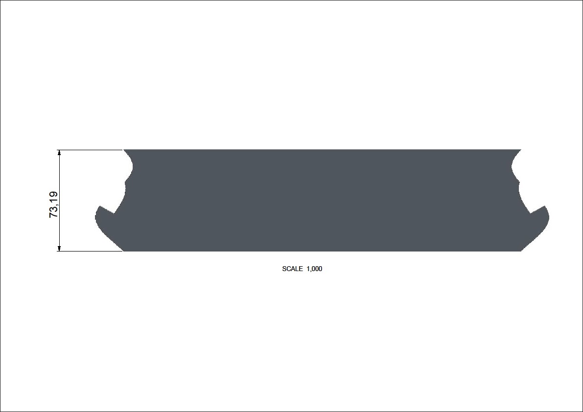
Jul 11, 2014
04:46 PM
- Mark as New
- Bookmark
- Subscribe
- Mute
- Subscribe to RSS Feed
- Permalink
- Notify Moderator
Please log in to access translation
Jul 11, 2014
04:46 PM
Sagar,
You need to use correct orientation of part in view to get correct value.
You can create new view in part or in drawing change the orientaion of view using Geometry references in View properties.
