Community Tip - You can change your system assigned username to something more personal in your community settings. X
- Community
- Creo+ and Creo Parametric
- Customization
- Did you know about color formats for CAM
- Subscribe to RSS Feed
- Mark Topic as New
- Mark Topic as Read
- Float this Topic for Current User
- Bookmark
- Subscribe
- Mute
- Printer Friendly Page
Did you know about color formats for CAM
- Mark as New
- Bookmark
- Subscribe
- Mute
- Subscribe to RSS Feed
- Permalink
- Notify Moderator
Did you know about color formats for CAM
When writing electrode data for CAM in IGES- or STEP-format it's sometimes necessary to set specific colors for solid surfaces to simplify programming. SMARTElectrode offers a dedicated function for this.
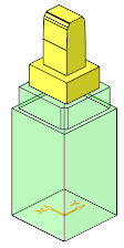
Task
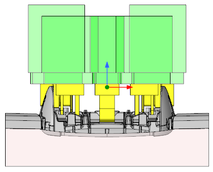
For example we would like to separate the electrode base from any electrode geometry.
Electrode geometry: yellow (RGB-code 255/255/0)
Electrode base: green with transparency (RGB-code 0/255/0; Transparency 80%)
At first we need to add an empty text file to the configuration. For example 'my_color_format.cfg'. Now the file should be opened in any text editor to add the rules for the coloration. The color format file needs following information in tab-delimited columns:
- What do you want to color
- A keyword or distinctive feature
- RGB color code
- Transparency
Listing of the format file
|
What do you want to color |
Keyword |
RGB color-code |
Transparency |
Description |
| EDM | -1 | 255,255,000 | - | Default color for all electrode models |
| FEATURE |
SE_BASE |
000,255,000 | 0.8 | Color for electrode base |
Usage in SMARTElectrode
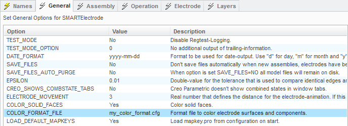
| 1. |
Open options UI and set file name |
 |
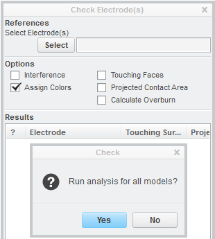
| 2. |
Open check UI Activate 'Assign Colors' Activate 'Start Calculation' Press 'Yes' Close dialog with 'OK' |
 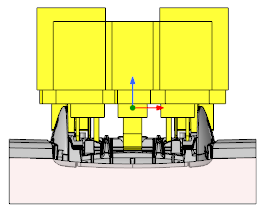 |
| 3. |
Result |
 |
Now let's use the STEP-export configuration from Did you know about STEP/IGES-export for CAM and import one of the files in Creo Parametric again.
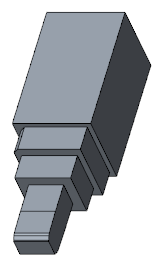
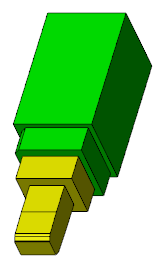
Gosh!? What happended here? - All surface colors are gone in the export.
After some investigation it's clear that some Creo options need specific settings.
step_appearance_layers_groups=yes should be used with step_export_format=ap203_is*.
step_appearance_layers_groups=no should be used with step_export_format=ap214_is.
After a 2nd run of the export functionality the import looks like expected.
Explanation of format file
What do you want to color?
Use EDM to set electrode model colors or use FEATURE to set the color for a specific SMARTElectrode feature or a named feature. There are some more values available that will be explained in one of the following posts.
Keyword or distinctive feature
For coloration of electrode models (EDM) the keyword should be the current number of the electrode or -1 as default color. For the coloration of features the feature name (no default names) should be used or one of feature names SMARTElectrode provides:
- SE_COPY_BURNFACES - selected burn-faces.
- SE_SOLID_IMPORT - solid used for cutout.
- SE_CUTOUT - surfaces cut from reference part.
- SE_ATTACH - connection between electrode solid and base.
- SE_SUPPORT - supporting geometry.
- SE_BASE - the electrode base.
RGB color code
Use integers from 0..255 for the color code. The color values must have a width of 3 digits each and should be separated by comma: RRR,GGG,BBB.
Transparency
Use - for no transparency or a decimal number in the range from 0 to 1.0 to define a transparency from 0% to 100%.
Attached file can be used with SMARTElectrode to comprehend the current article.
This thread is inactive and closed by the PTC Community Management Team. If you would like to provide a reply and re-open this thread, please notify the moderator and reference the thread. You may also use "Start a topic" button to ask a new question. Please be sure to include what version of the PTC product you are using so another community member knowledgeable about your version may be able to assist.
- Labels:
-
SMART Products


