

How to do "carve-out modeling" or "sub-modeling" with beams?
Hi everyone.
We to solve a problem with large frame-type models. The idea is to claculate a whole frame using idealized beams first, obtain resultant forces in certain parts and apply equivalent forces on solid models afterwards. How to do it?
I started from testing the functionality of Creo Simulate 2.
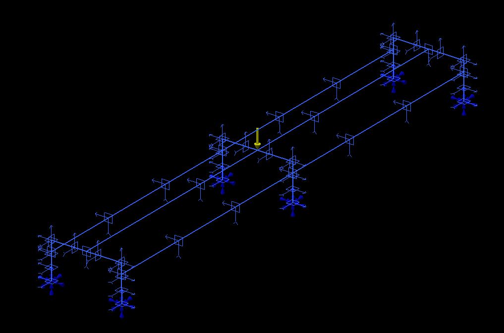
Firstly, I created a test frame, where beams were created using sketched curves and datum curves.
Creo Simulate model:
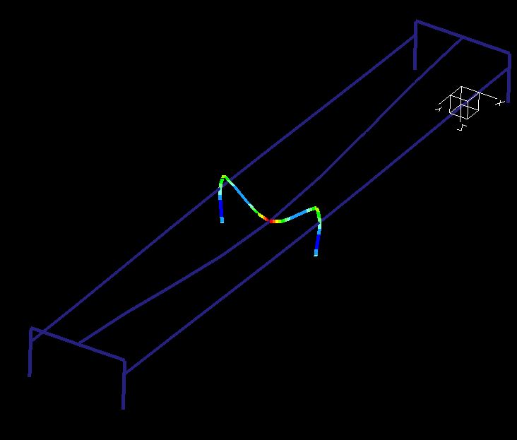
Results window - stress Von Mises:
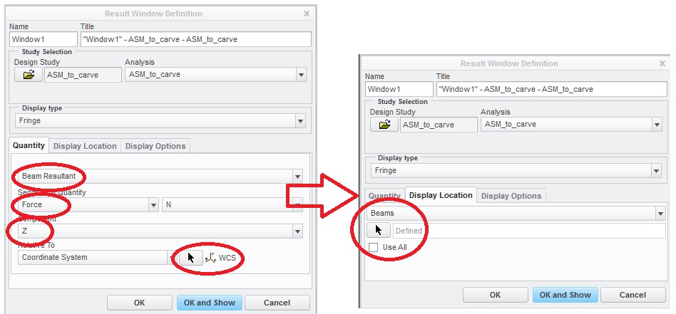
I am interested in obtaining forces in the central C - frame, which is most loaded. When I go for Beam Resultant - Force - Y and choose the frame, I obtain some results, which I am not able to interpret.
While applied vertical force along Z direction is 7500 N, fringe image shows two opposite resultant forces.
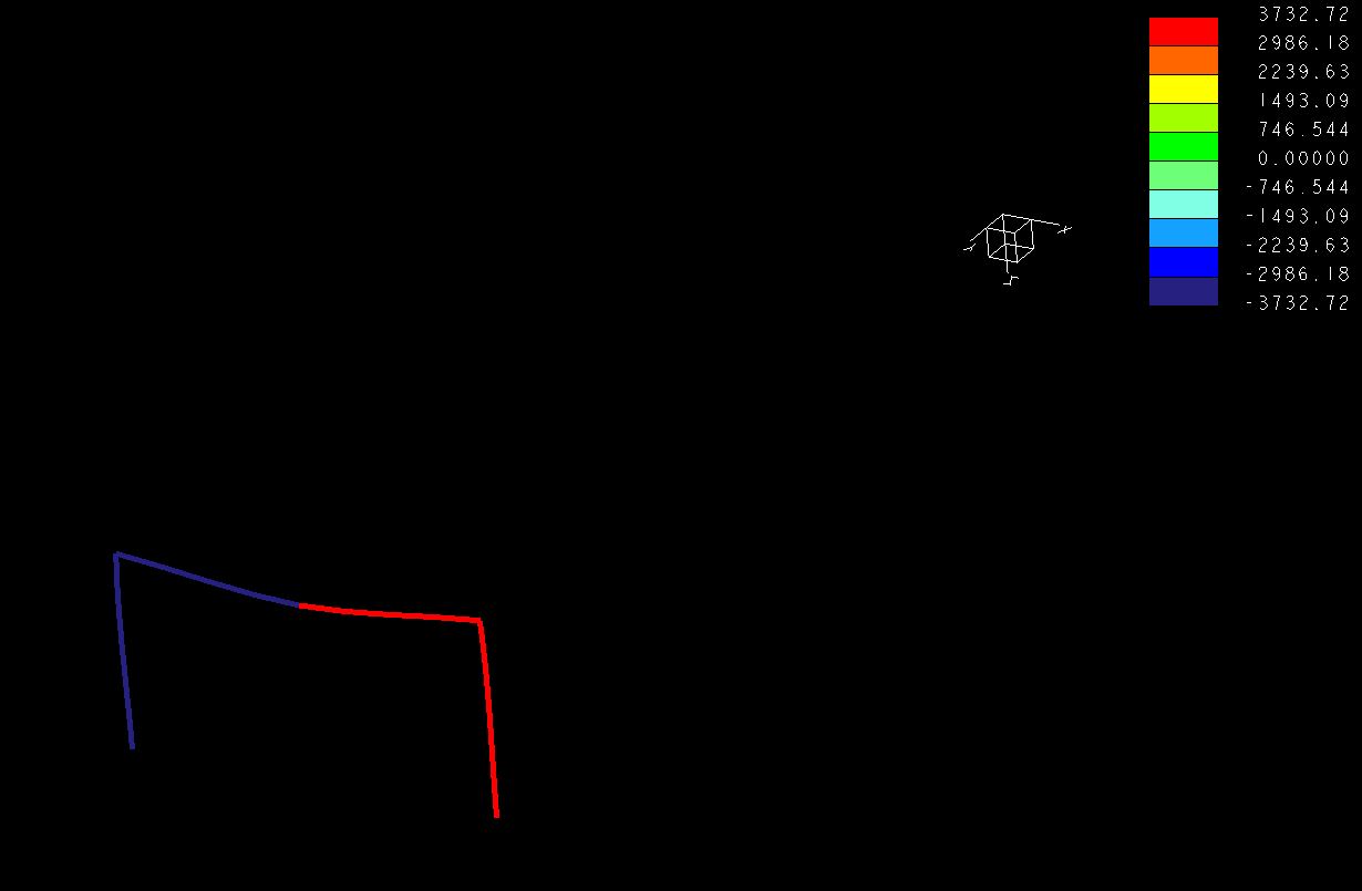
The resultant forces along X axis look bizzare as well:
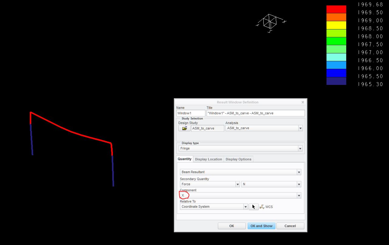
What does that all mean? I just want to find out where can I obtain correct resultant forces and on what areas should I apply them?
Thanks a lot in advance, the
Mikhail
This thread is inactive and closed by the PTC Community Management Team. If you would like to provide a reply and re-open this thread, please notify the moderator and reference the thread. You may also use "Start a topic" button to ask a new question. Please be sure to include what version of the PTC product you are using so another community member knowledgeable about your version may be able to assist.