Community Tip - Did you get an answer that solved your problem? Please mark it as an Accepted Solution so others with the same problem can find the answer easily. X
- Community
- Creo+ and Creo Parametric
- Customization
- auto bounding box in drawing?
- Subscribe to RSS Feed
- Mark Topic as New
- Mark Topic as Read
- Float this Topic for Current User
- Bookmark
- Subscribe
- Mute
- Printer Friendly Page
auto bounding box in drawing?
- Mark as New
- Bookmark
- Subscribe
- Mute
- Subscribe to RSS Feed
- Permalink
- Notify Moderator
auto bounding box in drawing?
Good morning all.
In my company, whenever I create a flat sheetmetal product, I'm going to have to make a drawing containing envelop dimensions to plot as PDF for reference and a second drawing with the flat-state scaled 1:1 to plot as dxf (which is used for the cam process).
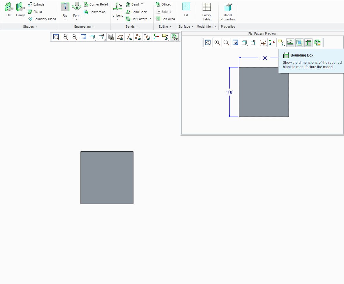
Since CREO there's this great feature in the "flat pattern preview" called bounding box (when in sheetmetal mode).
This shows the envelop size of a flat sheetmetal part.
Now wouldnt it be logical if drawing mode would have the same functionality?
Everytime I create a sheetmetal drawing (PDF) I have to add these dimensions manually.
Also it would be great if I could select drawing paper size that is slightly larger than the dimensions of the bounding box so when I press the Refit button, the part fits nicely on my screen (to be plotted as dxf, so I need scale 1:1).
any comments?

This thread is inactive and closed by the PTC Community Management Team. If you would like to provide a reply and re-open this thread, please notify the moderator and reference the thread. You may also use "Start a topic" button to ask a new question. Please be sure to include what version of the PTC product you are using so another community member knowledgeable about your version may be able to assist.
Solved! Go to Solution.
- Labels:
-
General
Accepted Solutions
- Mark as New
- Bookmark
- Subscribe
- Mute
- Subscribe to RSS Feed
- Permalink
- Notify Moderator
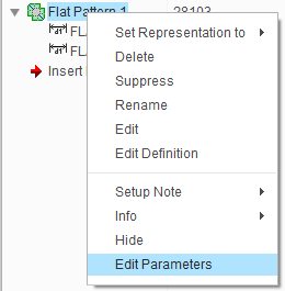
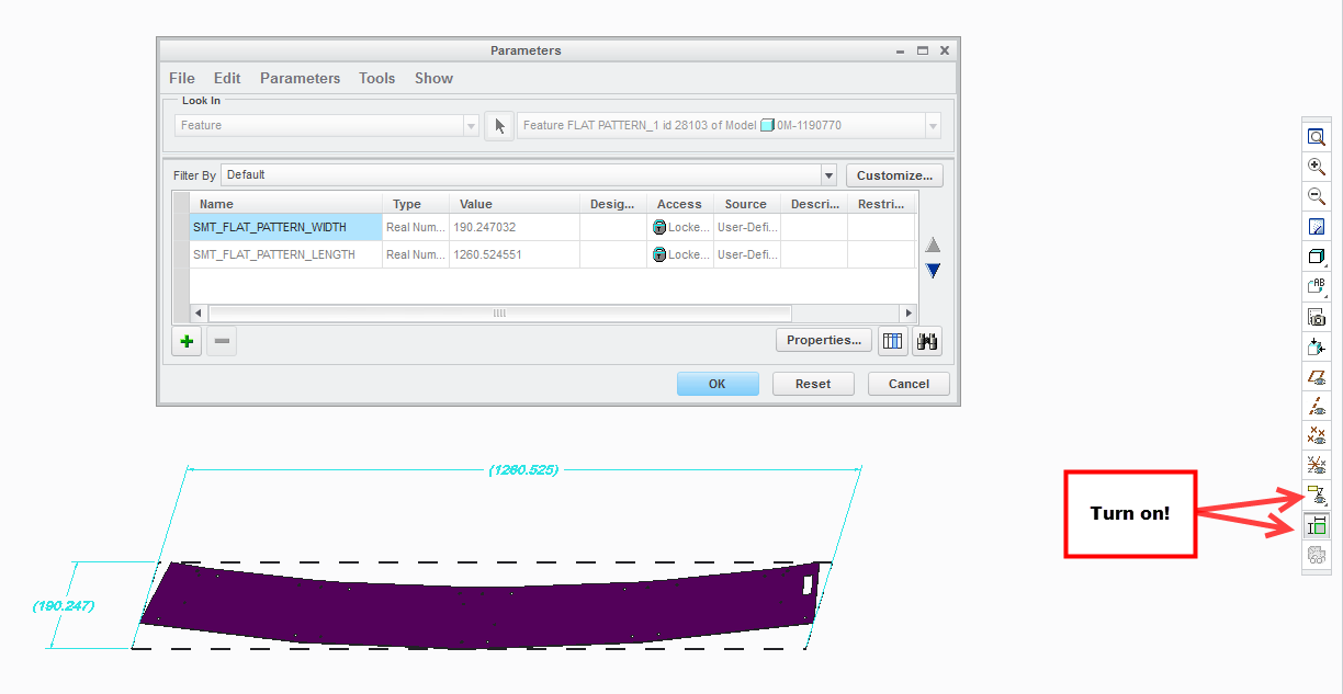
If you look in the flat pattern feature, you can see there are parameters in that feature. they should be like below.


You can pull those parameters into notes or symbols or those types of things.
- Mark as New
- Bookmark
- Subscribe
- Mute
- Subscribe to RSS Feed
- Permalink
- Notify Moderator
I'm also trying to utilize this feature. We have a relations in our sheet parts that fill in a filed on the drawing for thickness, flat length, & flat width. These are currently either manually tied to a dimension symbol or a value just entered manually. I want these to automatically be filled via bounding box dimensions.
I have found that if you create a flat pattern you get 2 feature parameters for lenth/width. ref: http://support.ptc.com/appserver/wcms/relnotes/note.jsp?&im_dbkey=135239&icg_dbkey=826
but i am having trouble getting those parameters to report, possibly because they are at the feature level instead of the part.
Also, if you click "switch dimensions" when viewing the bounding box preview you will see 2 dimension symbols pxxx and pxxx (it is buggy and hard to get them to show correctly but they're there). So I've tried using these symbols to populate my fields, but the actual number of that pxxx symbol is unpredictable (might be p122 & p123 or p627 & p628, and so on).
So, does anybody have any hints on how to put these bounding box values into a relation automatically and consistently?
thanks
- Mark as New
- Bookmark
- Subscribe
- Mute
- Subscribe to RSS Feed
- Permalink
- Notify Moderator
I'm going to suggest making some reference dimensions in the flat state and give them a reserved symbol name so you can find them easily. Even though they are reference, you can remove the reference annotation and manage their precision, along with any other annotation required.
You could create these dimensions by doing an unfold and creating a bounding sketch with associativity to the part. That sketch could be specifically created to create a geometry point feature in the lower left corner to manage the position of the DXF view on the page, so the view always grows up and right. Just add a Bend Back feature afterward if you want this within the history considering flat patterns are always last.
There are a number of ways to manage flat pattern features but I never liked them being the last feature because I want the generic to be as-used. This means the flat pattern is a "special case". How are you managing these?
Automating sheet size? Now your asking a lot ![]() You'd think this is possible.
You'd think this is possible.
- Mark as New
- Bookmark
- Subscribe
- Mute
- Subscribe to RSS Feed
- Permalink
- Notify Moderator
That's roughly how we do it now. Far from an automatic process.
- Mark as New
- Bookmark
- Subscribe
- Mute
- Subscribe to RSS Feed
- Permalink
- Notify Moderator
If you look in the flat pattern feature, you can see there are parameters in that feature. they should be like below.


You can pull those parameters into notes or symbols or those types of things.


