
Turn on suggestions
Auto-suggest helps you quickly narrow down your search results by suggesting possible matches as you type.
Showing results for
Please log in to access translation
Turn on suggestions
Auto-suggest helps you quickly narrow down your search results by suggesting possible matches as you type.
Showing results for
Community Tip - Your Friends List is a way to easily have access to the community members that you interact with the most! X
- Community
- Creo+ and Creo Parametric
- Manufacturing (CAM)
- Deform area on a Thread forming punch in sheetmeta...
Translate the entire conversation x
Please log in to access translation
Options
- Subscribe to RSS Feed
- Mark Topic as New
- Mark Topic as Read
- Float this Topic for Current User
- Bookmark
- Subscribe
- Mute
- Printer Friendly Page
Deform area on a Thread forming punch in sheetmetal
Jan 18, 2013
07:26 PM
- Mark as New
- Bookmark
- Subscribe
- Mute
- Subscribe to RSS Feed
- Permalink
- Notify Moderator
Please log in to access translation
Jan 18, 2013
07:26 PM
Deform area on a Thread forming punch in sheetmetal
Hi folks,
I can't say that I'm the most proficient at using the "deform area" tool, so maybe this is easy.
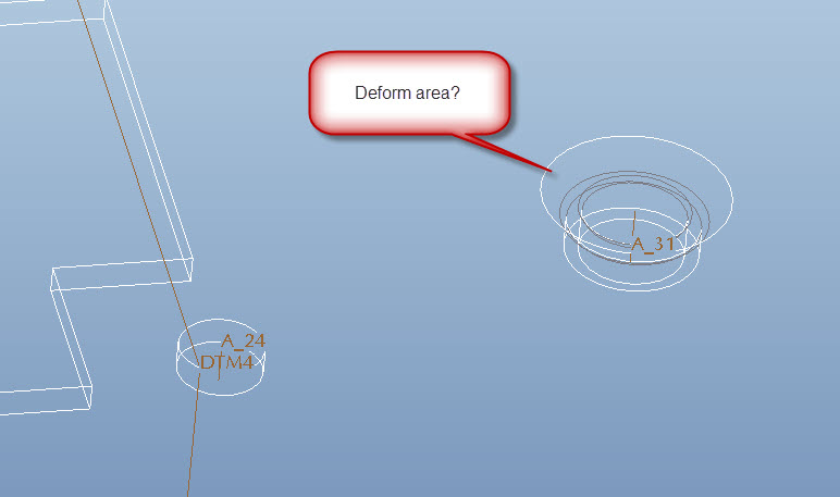
Can anybody get the Deform Area functionality to work for this thing?
Is it more common to create a datum point and note for the location and name of the tool for this feature when sending to manufacturing?
TYIA,
Josh
This thread is inactive and closed by the PTC Community Management Team. If you would like to provide a reply and re-open this thread, please notify the moderator and reference the thread. You may also use "Start a topic" button to ask a new question. Please be sure to include what version of the PTC product you are using so another community member knowledgeable about your version may be able to assist.
18 REPLIES 18
Jan 18, 2013
08:50 PM
- Mark as New
- Bookmark
- Subscribe
- Mute
- Subscribe to RSS Feed
- Permalink
- Notify Moderator
Please log in to access translation
Jan 18, 2013
08:50 PM
This one got me too. Seems difficult to thin the material in Sheetmetal for the pierce and extrude. I ended up making the part outside of Sheetmetal. I'm sure there is a way, but every feature wanted to maintain the material thickness. Since this is not the case with the pierce (it thins as it extrudes), it mattered to me.
Personally, I model that I see. So when I place these kinds of features, I also want to see them. It is too easy to overlook this at a higher level design review and suddenly you find yourself with an interference in the real parts.
Some tips with regard to this in Sheetmetal would be helpful indeed.
Jan 21, 2013
02:15 AM
- Mark as New
- Bookmark
- Subscribe
- Mute
- Subscribe to RSS Feed
- Permalink
- Notify Moderator
Please log in to access translation
Jan 21, 2013
02:15 AM
I actually do not think you can have anything in sheet metal that deviates frrom the standard material thickness unless it's in an area where there's relief. I cannot think of a single instance where I was able to use sheet metal mode to simulate the kind of deformity Joshua is trying to do here. I've always modeled this in regular Pro/E (or Creo).
For example... if I'm designing something that's vacu-formed and I need to show thinning accurately, I take it outside of sheetmetal. Or... if I decide to stay in sheetmetal mode, I add something to the drawing to let the manufacturing vendor know that thinning is acceptable in certain areas. Then I add local notes to point to the areas where thinning is expected/permitted.
Jan 21, 2013
12:31 PM
- Mark as New
- Bookmark
- Subscribe
- Mute
- Subscribe to RSS Feed
- Permalink
- Notify Moderator
Please log in to access translation
Jan 21, 2013
12:31 PM
Hmmm, guess I'll try to replace this feature with a regular Pro/E formed feature and see if I can get anywhere close. This is geometry that has been translated from another tool. I'm not sure if there was a flat pattern for it before, but I'm pretty sure we'll have to have it in the future.
I know at the TC's, we have discussed with PTC about introducing manufacturing features that produce variable thickness (deep drawing, plastic deformation, etc.), but the technology just wasn't readily available.
Thanks for the feedback Antonius and Brian. It's good to have some validation.
Jan 21, 2013
02:34 PM
- Mark as New
- Bookmark
- Subscribe
- Mute
- Subscribe to RSS Feed
- Permalink
- Notify Moderator
Please log in to access translation
Jan 21, 2013
02:34 PM
I had run into a model once that might be of interest. There is a way to "compress" an assembly into a part model. I will see if I can post more on this. I do not know if this will work with a sheetmetal model but if I recall correctly, that is where it was used.
Let me get back to you on this. This capability interests me very much as well.
Jan 21, 2013
02:48 PM
- Mark as New
- Bookmark
- Subscribe
- Mute
- Subscribe to RSS Feed
- Permalink
- Notify Moderator
Please log in to access translation
Jan 21, 2013
02:48 PM
I found the reference and yes, it is done in sheetmetal.
Have look in the help (and knowledgebase, if you have it) on External Inheritance
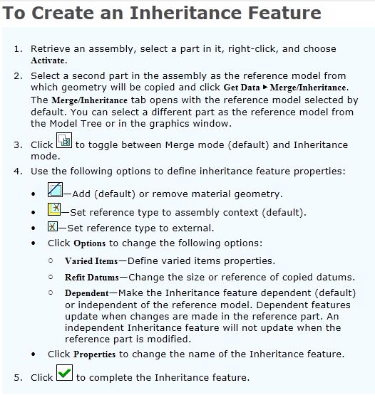
From the help files:
External Inheritance Features
An external Inheritance feature allows one-way associative propagation of geometry and feature data from a reference part to a target part without the need for assembly context. External Inheritance features are useful when representing the evolution of a design during manufacturing or when creating standard design elements.You can use external Inheritance features to either add or subtract material from the reference part geometry to or from a target part. Define the location of geometry propagated from the reference part by selecting coordinate systems on the reference and target parts.
A target part can contain one or more external Inheritance features. Features propagated from the reference part are represented in the target part as subfeatures of the external Inheritance feature. You can create a reference pattern in the target part based on the pattern of external Inheritance subfeatures.
Dimensions propagated from the reference part are fully accessible in Assembly, Part, and Detailed Drawings. These dimensions can be shown in a drawing of the target part.
Varied items and external Inheritance feature capabilities are identical to standard Inheritance features.
I have not used this yet but as said, I am very interested in how well this works for this type of scenario. I am not certain I am free to share the file where I found this, so my apologies for not providing that.
Jan 21, 2013
03:03 PM
- Mark as New
- Bookmark
- Subscribe
- Mute
- Subscribe to RSS Feed
- Permalink
- Notify Moderator
Please log in to access translation
Jan 21, 2013
03:03 PM
For completeness' sake: from the help files -
Jan 21, 2013
03:43 PM
- Mark as New
- Bookmark
- Subscribe
- Mute
- Subscribe to RSS Feed
- Permalink
- Notify Moderator
Please log in to access translation
Jan 21, 2013
03:43 PM
Hi Antonius, I'm familiar with Inheritance Features 
You might be interested in the attached document...it's a little old, but hopefully still relevant.
Jan 21, 2013
04:00 PM
- Mark as New
- Bookmark
- Subscribe
- Mute
- Subscribe to RSS Feed
- Permalink
- Notify Moderator
Please log in to access translation
Jan 21, 2013
04:00 PM
Good information, Joshua. Thanks.
Jan 21, 2013
03:59 PM
- Mark as New
- Bookmark
- Subscribe
- Mute
- Subscribe to RSS Feed
- Permalink
- Notify Moderator
Please log in to access translation
Jan 21, 2013
03:59 PM
I played around with the "Flatten Form" feature a little, (I'm somewhat rusty in this area).
It works as I recall in being able to flatten a feature that is formed by Pro/E (Creo) functionality.
The kicker is that Creo doesn't create a realistic sheetmetal feature in that there is no true deformation of a material.
I think it would normally be acceptable. Obviously it's going to create a slight variance in the mass properties and there might be the perception that it is something other than a formed sheetmetal feature.
Jan 21, 2013
10:22 PM
- Mark as New
- Bookmark
- Subscribe
- Mute
- Subscribe to RSS Feed
- Permalink
- Notify Moderator
Please log in to access translation
Jan 21, 2013
10:22 PM
Today I had a great opportunity to see how this could best be done. Indeed, there are some -serious- limitations to making features part of the base material in Sheetmetal.
1st I tried the Inheritance Features. I could not get anything to merge with the base sheetmetal part. So I thought, "great, I can make Sheetmetal PEMS and use the as Inheritance features..." NOT. Make a pierce and extrude sheetmetal part and "merge"... NOT The ladder could be inherited but you could not join it to the main model.
So I have never used Form features, until today. Mind you, I am using Creo 2.0 and I have done some sheetmetal model types with good success.
I looked at Joshua's linked model and the 1st thing I noticed is that it doesn't have the "1st wall" feature. This is key to beginning any sheetmetal model. Second, What am I missing here... I cannot see any history in release M030(?) (tools/investigate/model history; we've discussed this before). Lastly, I cannot see any features as they are created from Pattern 9 (unpattern\ungroup) only when the Solidify is applied to I see anything.
So on one of my Creo 2.0 sheetmetal parts I use the "half shear" tutorial to help me learn about form features. I successfully make it work and find I can easily make the feature represented in the initial post. So I do that; reduce the OD if the extruded wall (made with the form feature); add fillet radii to the inside base and the outside thread hole; next apply a cosmetic thread. I do all this in an "unbend" state. I reactivate the Bend Back and the feature moves with the wall as expected.
So a form feature seems to do what you want. You can do more operations to that form feature that are more core feature operations. If you have a lot of these to do, you'll find that they do not pattern, necessarily.
The moral of the story, always generate a "1st wall" feature be it planer or revolve. And create this after the initial datum features.
Jan 21, 2013
11:45 PM
- Mark as New
- Bookmark
- Subscribe
- Mute
- Subscribe to RSS Feed
- Permalink
- Notify Moderator
Please log in to access translation
Jan 21, 2013
11:45 PM
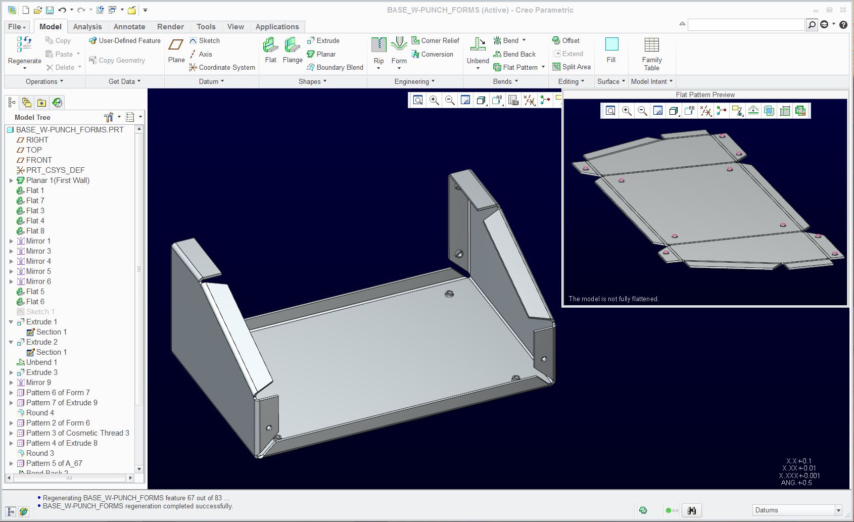
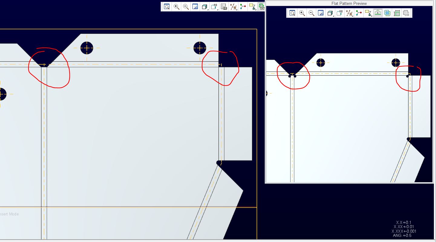
I have added a Creo 2.0 model of a sheetmetal base with pierce and extrude 4-40 threads replacing PEMs installed at a next level.
Feel free to review it if you can open it. Again, I learned quite a few new things about sheetmetal (do's and don'ts) like what patterns correctly and what doesn't (reference patterns). As with all versions of Pro/E, the cosmetic threads don't follow folds and unfolds unless they are in the 1st wall. You have to play with the layers to have the form tool datums turn off (you cannot select them to hide). You will see what patterned successfully and what failed in the attached file.
Jan 22, 2013
01:08 AM
- Mark as New
- Bookmark
- Subscribe
- Mute
- Subscribe to RSS Feed
- Permalink
- Notify Moderator
Please log in to access translation
Jan 22, 2013
01:08 AM
Hey there Antonius, a couple of tips...
1. The sheetmetal part with the forms actually started out as a solid that was translated from another CAD program. I moved up the model tree until the geometry was acceptable to turn into sheetmetal.
2. Historically, inheritance features have to be the same type (sheetmetal or solid). It's likely you were trying to insert solid geometry into a sheetmetal part, or vice versa.
Took a look at your "base_w-punch_forms.prt" file. Nice work!
Have you tried the "Flatten Form" functionality? I couldn't get it working since I didn't have your form part.
Jan 22, 2013
02:09 AM
- Mark as New
- Bookmark
- Subscribe
- Mute
- Subscribe to RSS Feed
- Permalink
- Notify Moderator
Please log in to access translation
Jan 22, 2013
02:09 AM
Hi Antonius...
You can definitely...definitely make the thing with the PEMs work. I've done it before to create a part that appeared to be an inseparable assembly. Of course, I used inheritance features exactly as you and Joshua both suggested.
Speaking to Joshua's point, one of my personal "best practices" for working with sheet metal parts in Creo is to start them as solid models. I practically never start in sheet metal. I always have my base feature as a regular solid model and then use either the shell or thickness option to turn slip into sheet metal mode. Obviously in this case Joshua's model was imported from another system but I use this technique even when that's not the case.
What does it buy you? It's tough to describe in words... but imagine you're trying to make a 5-sided box in sheet metal so it can be unfolded. You'd like to be able to capture the height, width, and length of the box as driving dimensions. You can always get two of these dimensions easily in your first sheet metal feature... but you can't get the third. To get that third dimension, you have to jump through hoops. Yet in solid mode you can simply make an extrusion with the correct 3 dimensions. So... I use each mode for its strengths- solid mode for easily capturing those initial dimensions and sheet metal mode for all the walls, bending, and flattening. Look into the Sheet Metal Conversion feature and the Edge Bend feature... these are both tremendously helpful for performing solid-to-sheet metal conversions.
Take care...
-Brian
Jan 22, 2013
02:29 AM
- Mark as New
- Bookmark
- Subscribe
- Mute
- Subscribe to RSS Feed
- Permalink
- Notify Moderator
Please log in to access translation
Jan 22, 2013
02:29 AM
Brian, making the box the size I wanted wasn't too much trouble. Even a nice round number for the tilted face wasn't too bad.
The PEM wouldn't inherit regardless of what I did. The half shear as a sheetmetal part also wouldn't merge. It just kind of floated in the model. Poor form. I am glad I was able to create -exactly- what I wanted in the end.
Flattening the form feature is likely failing because I cut the feature after the fact, and added the radii -I- wanted. Without those features, it would probably flatten just fine. BTW: the form feature was a simple rod at diameter .082".
Jan 22, 2013
02:58 AM
- Mark as New
- Bookmark
- Subscribe
- Mute
- Subscribe to RSS Feed
- Permalink
- Notify Moderator
Please log in to access translation
Jan 22, 2013
02:58 AM
If I remove the extra works on the form feature, they flatten fine.
then I run into a new M030 bug...
Jan 22, 2013
01:50 PM
- Mark as New
- Bookmark
- Subscribe
- Mute
- Subscribe to RSS Feed
- Permalink
- Notify Moderator
Please log in to access translation
Jan 22, 2013
01:50 PM
Interesting technique there Brian. I've always started out in sheetmetal if that was my intent.
Now, what if you started with a capped surface feature describing your initial geometry and then just creating the walls up to that extent...somewhat like a skeleton model technique?
Jan 22, 2013
02:10 PM
- Mark as New
- Bookmark
- Subscribe
- Mute
- Subscribe to RSS Feed
- Permalink
- Notify Moderator
Please log in to access translation
Jan 22, 2013
02:10 PM
There is a good tutorial on this if you have the Learning Connector, search for the following tutorial:
http://learningexchange.ptc.com/tutorial/410/using-the-conversion-tool
If you have the elearning, you can get the full access to the work files and such.
Of course, for some reason I can't seem to log into elearning 
Jan 29, 2013
01:30 PM
- Mark as New
- Bookmark
- Subscribe
- Mute
- Subscribe to RSS Feed
- Permalink
- Notify Moderator
Please log in to access translation
Jan 29, 2013
01:30 PM
I had an issue where a guy had tried to do something in sheetmetal and it almost worked, but I couldn't modify it at ALL. Like Brian said, once you pick a thickness you're done. I think sheetmetal should be an optional package, with the commands inside regular Pro/E, so if you did some sheetmetal part, and then machined some other area, or if you wanted something like sheetmetal (because you needed both folded and flat patterns) but it would in fact be an IM plast part (with bosses, which is impossible in sheetmetal). For me, since I needed a flat state, a state where just the leads were bent, and when the leads and the flex circuit was bent, I ended up having to do my part as a family table assembly of family table parts that all had spinal bend features in it to get what I needed. Something so simple ends up being so difficult......
Announcements


Top Tags
