
Turn on suggestions
Auto-suggest helps you quickly narrow down your search results by suggesting possible matches as you type.
Showing results for
Please log in to access translation
Turn on suggestions
Auto-suggest helps you quickly narrow down your search results by suggesting possible matches as you type.
Showing results for
Community Tip - Learn all about the Community Ranking System, a fun gamification element of the PTC Community. X
- Community
- Creo+ and Creo Parametric
- Manufacturing (CAM)
- cutcom does't work properly!
Translate the entire conversation x
Please log in to access translation
Options
- Subscribe to RSS Feed
- Mark Topic as New
- Mark Topic as Read
- Float this Topic for Current User
- Bookmark
- Subscribe
- Mute
- Printer Friendly Page
cutcom does't work properly!
Oct 22, 2015
03:28 AM
- Mark as New
- Bookmark
- Subscribe
- Mute
- Subscribe to RSS Feed
- Permalink
- Notify Moderator
Please log in to access translation
Oct 22, 2015
03:28 AM
cutcom does't work properly!
I want to use cutter compensation in a profilmilling sequence. I enabled the options for cutcom, witch prints G41/G42 in my tab file.
The problem is that already in the cl-file are the wrong coordinates. They are not influenced by turning the cutcom option on.
What can I do to get the right path for my cutter compensation?
(In the attachment is my little test project)
This thread is inactive and closed by the PTC Community Management Team. If you would like to provide a reply and re-open this thread, please notify the moderator and reference the thread. You may also use "Start a topic" button to ask a new question. Please be sure to include what version of the PTC product you are using so another community member knowledgeable about your version may be able to assist.
Solved! Go to Solution.
Labels:
- Labels:
-
General
ACCEPTED SOLUTION
Accepted Solutions
Oct 27, 2015
01:32 PM
- Mark as New
- Bookmark
- Subscribe
- Mute
- Subscribe to RSS Feed
- Permalink
- Notify Moderator
Please log in to access translation

9 REPLIES 9
Oct 22, 2015
11:32 AM
- Mark as New
- Bookmark
- Subscribe
- Mute
- Subscribe to RSS Feed
- Permalink
- Notify Moderator
Please log in to access translation
Oct 22, 2015
11:32 AM
I tried to open your files, but I can't because it was made with an educative license.
Have you specified the entry and exit movement to activate cutter compensation ?
Oct 22, 2015
01:17 PM
- Mark as New
- Bookmark
- Subscribe
- Mute
- Subscribe to RSS Feed
- Permalink
- Notify Moderator
Please log in to access translation
Oct 22, 2015
01:17 PM
Oh sorry I didn't know there is a difference between an educative license and an normal one .
I attached a screenshot of my part. As you can see i have specified the entry and exit movement.
In the cl-file you can find the codes like CUTCOM/ON and ../OFF, but in the posted coordinates there is the cutter diameter included already.
Am I right that it should post the geometry data for cutter compensation ?
Thank you in advance!
Oct 22, 2015
03:48 PM
- Mark as New
- Bookmark
- Subscribe
- Mute
- Subscribe to RSS Feed
- Permalink
- Notify Moderator
Please log in to access translation
Oct 22, 2015
03:48 PM
I don't really use cutter compensation much, but my basic understanding of it is that it is interpreted by the milling machine. You generate movement code from Creo that is based upon the tools you defined in the manufacturing module. These coordinates are always the same. When you run the program, you set the appropriate registers on the machine to tell it that, though you programmed the thing for a 10mm endmill, it's actually using a 9.85mm one, etc. That's the reason for using cutter compensation; you can run the same program with a resharpened endmill and account for the smaller diameter.
If I'm mistaken on this, feel free to correct me, guys.
Oct 23, 2015
03:09 AM
- Mark as New
- Bookmark
- Subscribe
- Mute
- Subscribe to RSS Feed
- Permalink
- Notify Moderator
Please log in to access translation
Oct 23, 2015
03:09 AM
This is right Kenneth, I often use cutter compensation, this allows the workshop to adjust according to the tools diameter because we sometime use resharpened endmill and also when we mill parts with very thin tolerances.
Alexander, I reproduced your example and here is what I get (the plate is 150x100mm).
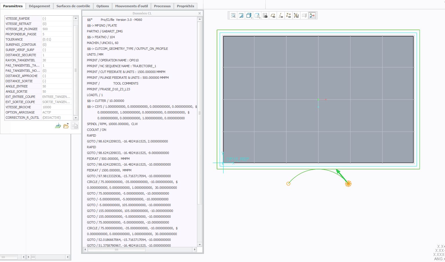
First without cutter compensation, we can see that the tool center is driven. So no matter what tool you get it will always follow the path defined by the center.
Then with cutter compensation on. We can see that the edge of the tool is driver. So, as Kenneth explained if a 12mm tool is used it will still follow the same path defined by it's edge.
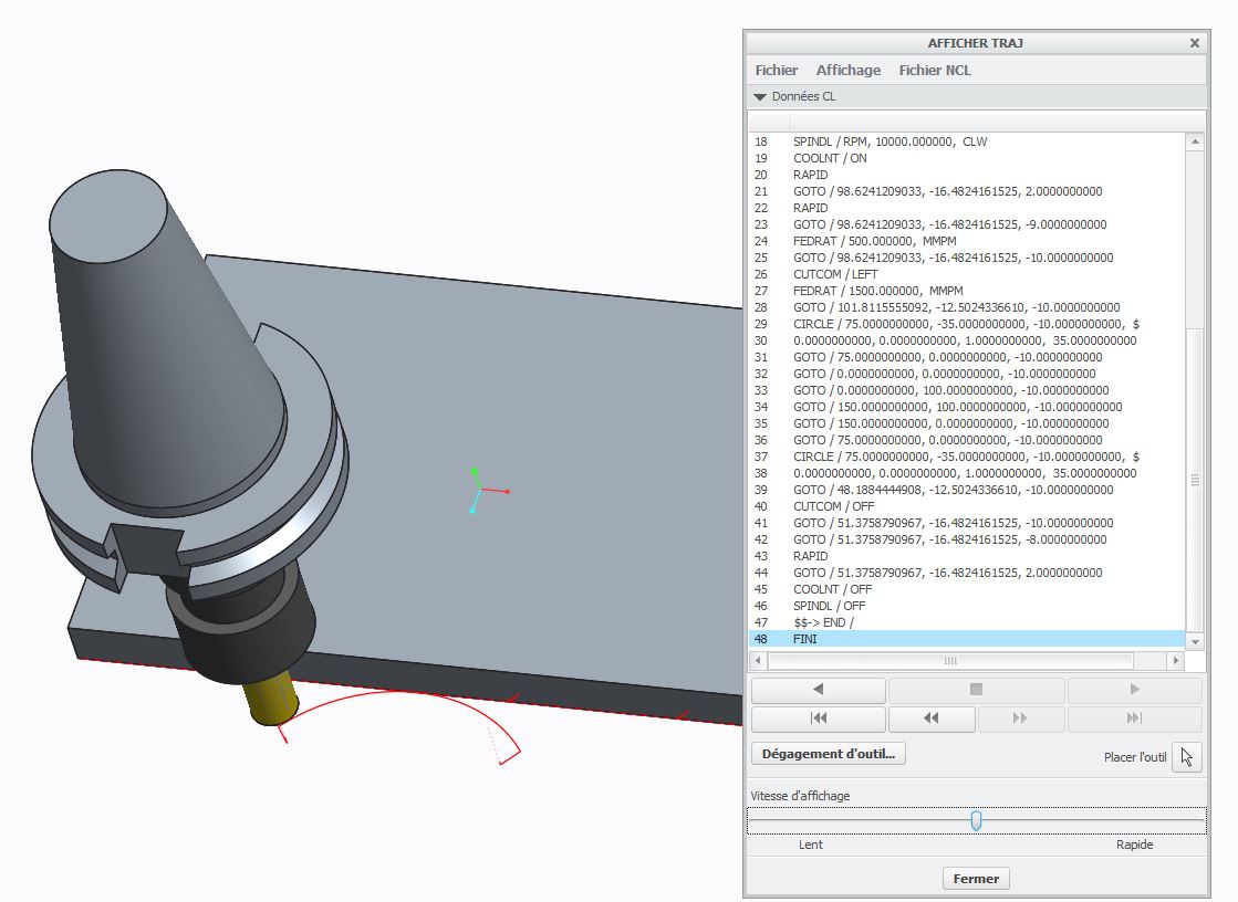
With those little tests, I noticed a bug. When tool compensation is on, if you look at the CL data using this button 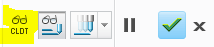 . The CL data is wrong, it shows like tool compensation was off. To see the correct CL date you need to play the path !!
Oct 27, 2015
01:04 PM
- Mark as New
- Bookmark
- Subscribe
- Mute
- Subscribe to RSS Feed
- Permalink
- Notify Moderator
Please log in to access translation
Oct 27, 2015
01:04 PM
First of all thank you for your efforts  But I still haven't success.
Can you send me the example file that you have created ?
Oct 27, 2015
01:32 PM
- Mark as New
- Bookmark
- Subscribe
- Mute
- Subscribe to RSS Feed
- Permalink
- Notify Moderator
Please log in to access translation
Oct 27, 2015
02:16 PM
- Mark as New
- Bookmark
- Subscribe
- Mute
- Subscribe to RSS Feed
- Permalink
- Notify Moderator
Please log in to access translation
Oct 27, 2015
02:16 PM
Thank you so much  I used the wrong operation. You used the Trajectory Milling instead of Profile Milling.
Now it works!
Oct 28, 2015
04:01 AM
- Mark as New
- Bookmark
- Subscribe
- Mute
- Subscribe to RSS Feed
- Permalink
- Notify Moderator
Please log in to access translation
Oct 28, 2015
04:01 AM
I'm pleased I helped you ! In fact, I never use Profile milling as you can do exactly the same things with Trajectory milling but in a much easier way from my point of view.
Oct 29, 2015
07:54 AM
- Mark as New
- Bookmark
- Subscribe
- Mute
- Subscribe to RSS Feed
- Permalink
- Notify Moderator
Please log in to access translation
Oct 29, 2015
07:54 AM
If you are using Profile sequence you will need to set these parameters for cutcom to work.
LEAD_RADIUS
TANGENT_LEAD_STEP
CUT_ENTRY_EXT to LEAD_IN
CUT_EXIT_EXT to LEAD_OUT
CUTCOM to ON
Announcements


Top Tags
