Community Tip - Need to share some code when posting a question or reply? Make sure to use the "Insert code sample" menu option. Learn more! X
- Subscribe to RSS Feed
- Mark Topic as New
- Mark Topic as Read
- Float this Topic for Current User
- Bookmark
- Subscribe
- Mute
- Printer Friendly Page
Circuit analysis
- Mark as New
- Bookmark
- Subscribe
- Mute
- Subscribe to RSS Feed
- Permalink
- Notify Moderator
Circuit analysis
I'm not exactly sure what is causing the error of if I'm doing something completely wrong
Circuit is shown 
- Mark as New
- Bookmark
- Subscribe
- Mute
- Subscribe to RSS Feed
- Permalink
- Notify Moderator
I am a bit confused about the initial conditions. As I see it both currents I1 and I2 would be zero for t=0 (which obviously should denote the close of the switch.
- Mark as New
- Bookmark
- Subscribe
- Mute
- Subscribe to RSS Feed
- Permalink
- Notify Moderator
Your second equation contents not derivatives but divisions and multiplications
- Mark as New
- Bookmark
- Subscribe
- Mute
- Subscribe to RSS Feed
- Permalink
- Notify Moderator
Assuming that the capacitor is fully discharged (Vc= 0) I think that it is possible to achieve 3mA load on the voltage source. this csn be split to initial currents of 2.5mA into the capacitor & 0.5mA into the inductor or just 3mA int the capacitor & 0 into the inductor.
This doesn't match with the schematic drawn, the cap here will be fully charged to 20V long before you can close the switch.
As to problems with the Mathcad sheet.
It is difficult to understand the relevance of the equations given, I would be tempted to re-write them as much simpler equations describing the node voltages & currents:
Vsw(itch & Vc(ap will suffice for the additional voltage nodes
& the currents
Iv (current out of the voltage source)
Ic (into the capacitor)
I.L (into the Inductor)
Defining variables such as R1: 5000 will also help to simplify the equations.
Regards
Andy
- Mark as New
- Bookmark
- Subscribe
- Mute
- Subscribe to RSS Feed
- Permalink
- Notify Moderator
Your second equation contents not derivatives but divisions and multiplications
- Mark as New
- Bookmark
- Subscribe
- Mute
- Subscribe to RSS Feed
- Permalink
- Notify Moderator
- Mark as New
- Bookmark
- Subscribe
- Mute
- Subscribe to RSS Feed
- Permalink
- Notify Moderator
There were a bunch of errors in your file which could have been easily avoided by using, reading and paying attention to Mathcads help files!
- As Valery pointed out you did not use the derivation operator in the second equation but simply typed a similar looking fraction
- for initial values you must use the prime character, not the derivation operator
- q1 would be first, q2 second order. So you need just three initial conditions, not six, as you try to provide.
- you used the Odesolve command the wrong way. As you had set up a system of ODEs with two functions, the first parameter of Odesolve() has to be a vector with the names of those functions.
- The result of Odesolve will be two (pseudo) functions, so on the LHS of the assignment you should provide an apropriate vector.
Furthermore, as was already stated, your initial conditions are definitely wrong, if we assume that t=0 would be the moment the switch is closed. All currents would be zero at that moment and the capacitor voltage could be assumed to be 20 V.
I also think that t=1 as endpoint is too big. After one second you will not see any more noticeable changes in your curcuit.
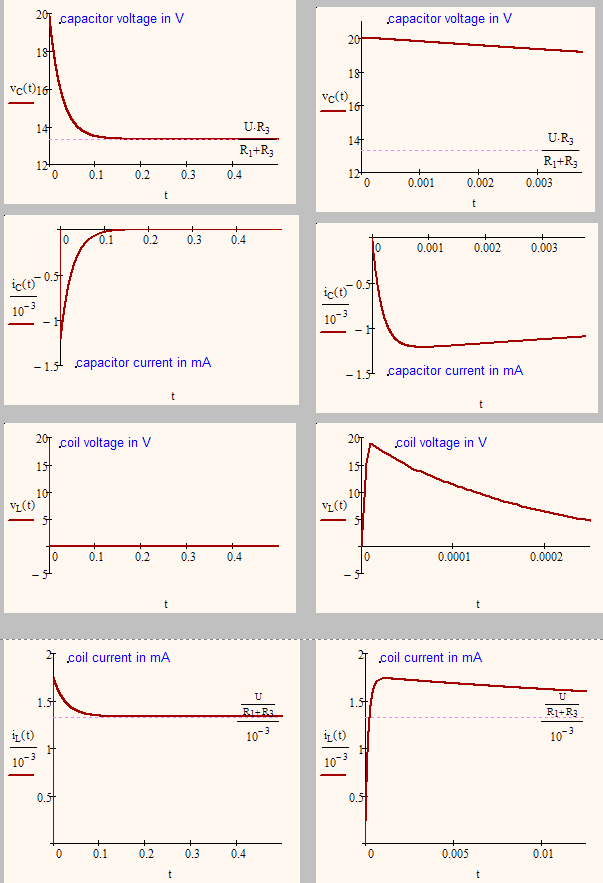
Nonetheless, Odesolve can be a stubborn beast and may be very sensible about the way you write your equations, So I have provided a solution to your problem but I followed a slightly different way in setting up the equations and throw overboard the charge functions. It seemed to me that you don't need them and their sole purpose was to get rid of the integral you get for the cap voltage.
- Mark as New
- Bookmark
- Subscribe
- Mute
- Subscribe to RSS Feed
- Permalink
- Notify Moderator
Fine work, Werner! I done someone for hydro circuits
I repeate it is a task for Prime.
But we can use pseudounits in M15 - see please the attach
- Mark as New
- Bookmark
- Subscribe
- Mute
- Subscribe to RSS Feed
- Permalink
- Notify Moderator
- Mark as New
- Bookmark
- Subscribe
- Mute
- Subscribe to RSS Feed
- Permalink
- Notify Moderator
Yeah, coil voltage during the first microsecond is interesting.
- Mark as New
- Bookmark
- Subscribe
- Mute
- Subscribe to RSS Feed
- Permalink
- Notify Moderator
All is interesting.
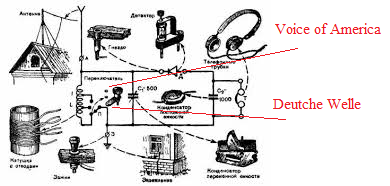
When I created this sheet in Prime I remembered my childhood, when I assembled my first crystal radio set...
Can we model this device now in Mathcad? ![]()
- Mark as New
- Bookmark
- Subscribe
- Mute
- Subscribe to RSS Feed
- Permalink
- Notify Moderator
Can we model this device in Mathcad
Feel free to do so 😉
Detector radios feom the "good old time" (really??).
The most simply one
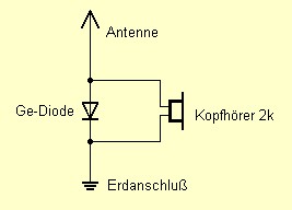
and the most chemical one (?)

But I think we should stop posting offtopics now or Zac will not be able to find the answer to his question amongst all the other postings - in case he still is interested.
- Mark as New
- Bookmark
- Subscribe
- Mute
- Subscribe to RSS Feed
- Permalink
- Notify Moderator
Sorry, last reply!
I have used one haft of potatoes as a electrolytic detector ![]()
- Mark as New
- Bookmark
- Subscribe
- Mute
- Subscribe to RSS Feed
- Permalink
- Notify Moderator
Werner Exinger wrote:
Yeah, coil voltage during the first microsecond is interesting.
Or Mathcad tools is interesting![]()
- Mark as New
- Bookmark
- Subscribe
- Mute
- Subscribe to RSS Feed
- Permalink
- Notify Moderator
Werner Exinger wrote:
Yeah, coil voltage during the first microsecond is interesting.
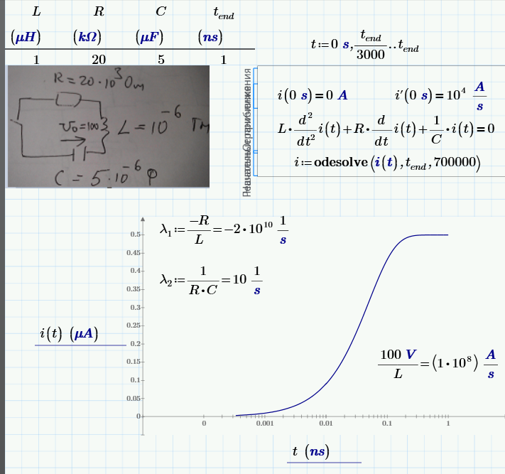
Stiff differential equations.
One other example:
- Mark as New
- Bookmark
- Subscribe
- Mute
- Subscribe to RSS Feed
- Permalink
- Notify Moderator
Valery Ochkov wrote:
Fine work, Werner! I done someone for hydro circuits
I repeate it is a task for Prime.
But we can use pseudounits in M15 - see please the attach
Thanks.
Your pseudounits are a nice idea but may be confusing if the worksheet is longer and you want to do calculations with real units afterwards, too. I'd rather strip the units for the solver and after odesolve did its work you may add them to the solutions via i.C(t):=i.C(t)*A. So the functions would yield real units to be used later.
As the originial post was w/o units I didn't bother doing so, though.
The better intgeration of units (matrices with units of different dimensions, use of units in odesolve, etc. ) sure is one of the very few advantages of Prime over MC15.
- Mark as New
- Bookmark
- Subscribe
- Mute
- Subscribe to RSS Feed
- Permalink
- Notify Moderator
Werner Exinger wrote:
- As Valery pointed out you did not use the derivation operator in the second equation but simply typed a similar looking fraction
Welcome to the Ward#28 in the Mathcad House:
- Mark as New
- Bookmark
- Subscribe
- Mute
- Subscribe to RSS Feed
- Permalink
- Notify Moderator
thanks for all the responses guys, I understand now from what Werner explained


