
Turn on suggestions
Auto-suggest helps you quickly narrow down your search results by suggesting possible matches as you type.
Showing results for
Please log in to access translation
Turn on suggestions
Auto-suggest helps you quickly narrow down your search results by suggesting possible matches as you type.
Showing results for
Community Tip - Want the oppurtunity to discuss enhancements to PTC products? Join a working group! X
Translate the entire conversation x
Please log in to access translation
Options
- Subscribe to RSS Feed
- Mark Topic as New
- Mark Topic as Read
- Float this Topic for Current User
- Bookmark
- Subscribe
- Mute
- Printer Friendly Page
How to solve this simple voltage summing circuit using Mathcad
Sep 24, 2016
09:16 PM
- Mark as New
- Bookmark
- Subscribe
- Mute
- Subscribe to RSS Feed
- Permalink
- Notify Moderator
Please log in to access translation
Sep 24, 2016
09:16 PM
How to solve this simple voltage summing circuit using Mathcad
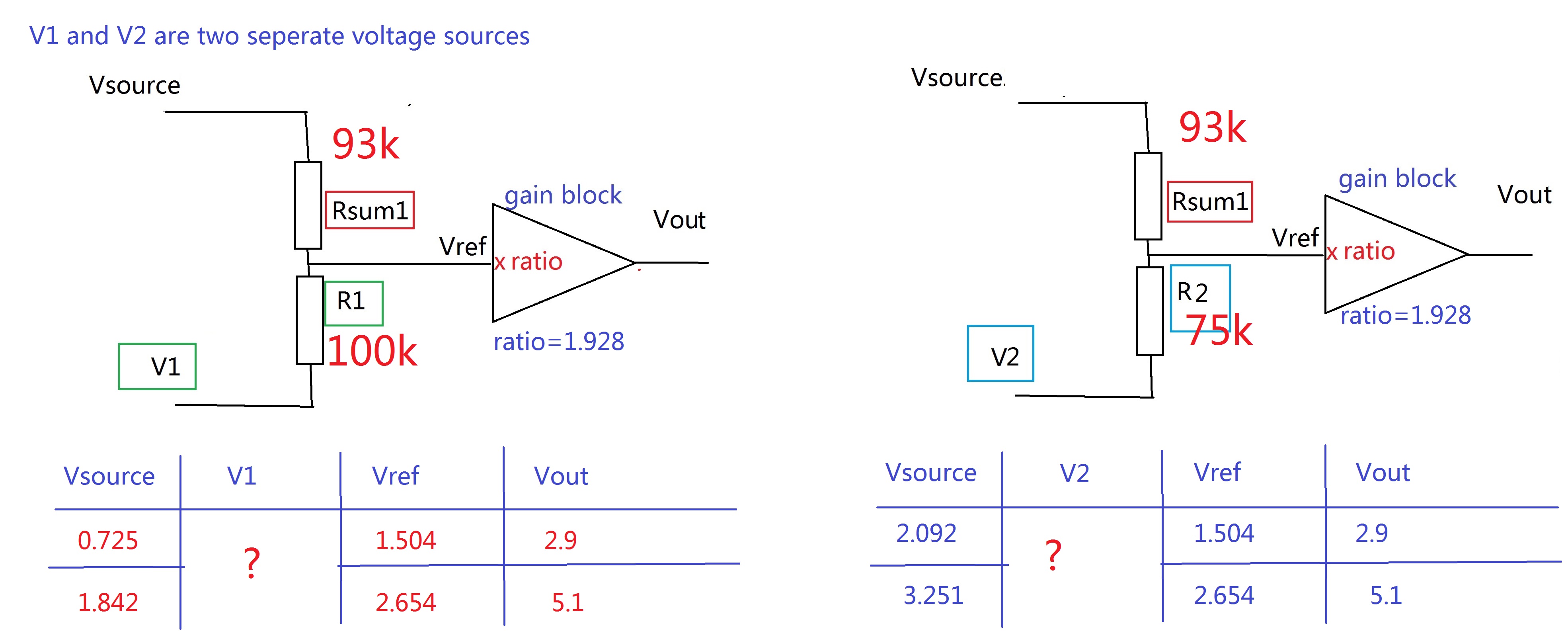
Hi All, I have a simple summing circuit. Two sources are the inputs via two resistors to generate a weighted signal Vref. Then this Vref is multiplying by a constant number "ratio" to get a Vout. The details of my circuit can be seen here:
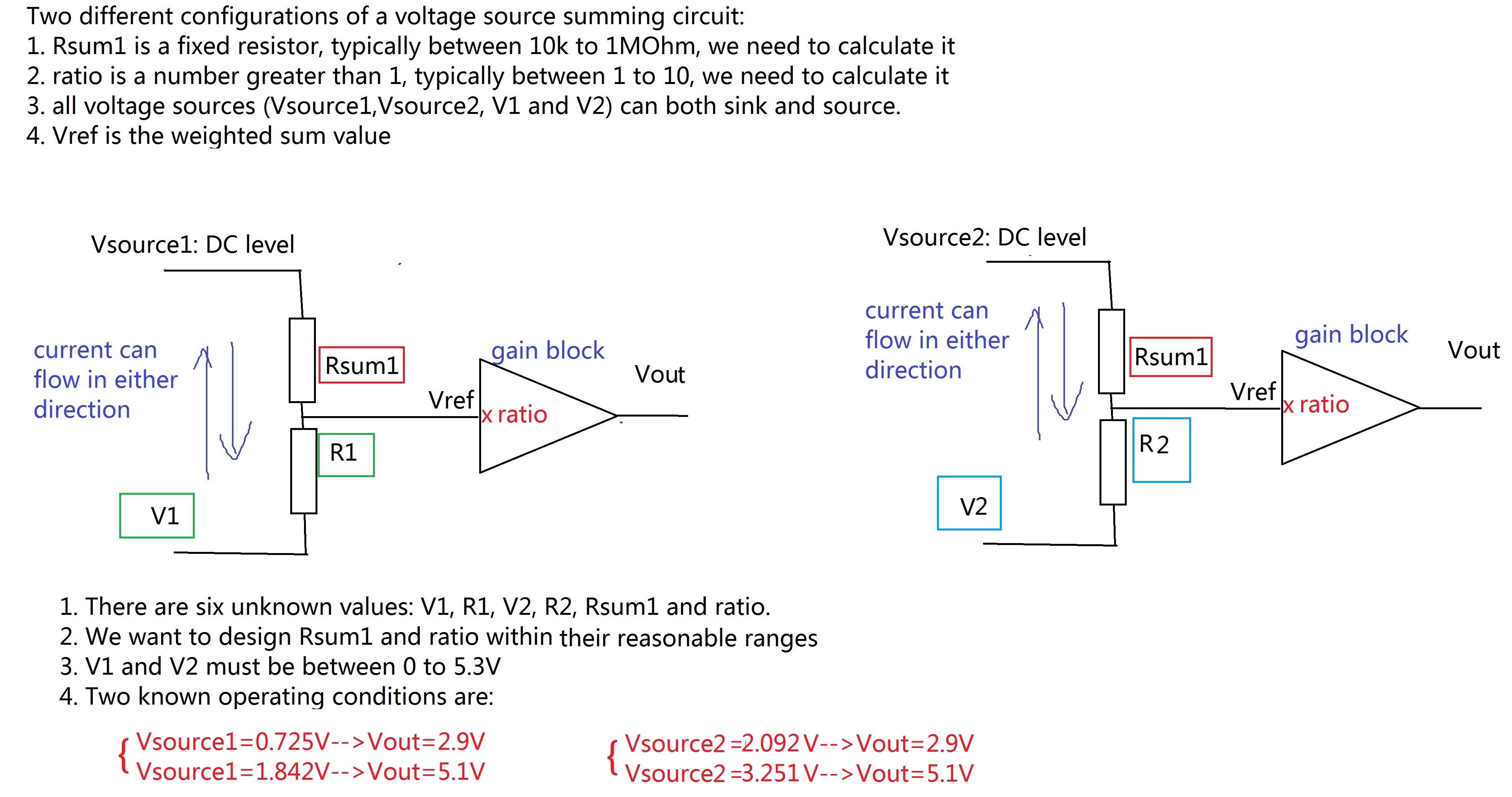
My target V1,V2 are within 0 to 5.3V, and target 10>"ratio">1, and all resistors should be between 10K to 1M ohm. Right now I am not able to use if condition to solve the equation array to figure out what V1,V2,R1,R2 are.
I have uploaded my worksheet in the attachment. Would anyone teach me how can I calculate these values within the reasonable range, by maintaining the other two parameters "ratio" and "Rsum1" within their reasonable range? Thank you!
Solved! Go to Solution.
Labels:
- Labels:
-
Other
78 REPLIES 78
Sep 26, 2016
01:35 PM
- Mark as New
- Bookmark
- Subscribe
- Mute
- Subscribe to RSS Feed
- Permalink
- Notify Moderator
Please log in to access translation
Sep 26, 2016
01:35 PM
Thank you Alvaro! Thank you for your help!
According to your results, V1=1.504V and V2=2.654V. But when I used V1=1.504V to calculate Vout when Vsource1=0.725V, the calculated result is 2.253V, instead of 2.9V. Am I missing something?
Sep 26, 2016
02:03 PM
- Mark as New
- Bookmark
- Subscribe
- Mute
- Subscribe to RSS Feed
- Permalink
- Notify Moderator
Please log in to access translation
Sep 26, 2016
02:03 PM
Sep 26, 2016
02:08 PM
- Mark as New
- Bookmark
- Subscribe
- Mute
- Subscribe to RSS Feed
- Permalink
- Notify Moderator
Please log in to access translation
Sep 26, 2016
02:08 PM
Hi Alvaro, I understand now. 1.504V and 2.645V are the Vref at two conditions, instead of V1 and V2. I need to use Vref and Vsource1 and Vsource2 to calculate back V1 and V2. Is it correct?
Sep 26, 2016
02:09 PM
- Mark as New
- Bookmark
- Subscribe
- Mute
- Subscribe to RSS Feed
- Permalink
- Notify Moderator
Please log in to access translation
Sep 26, 2016
02:09 PM
Yep.
Sep 26, 2016
02:16 PM
- Mark as New
- Bookmark
- Subscribe
- Mute
- Subscribe to RSS Feed
- Permalink
- Notify Moderator
Please log in to access translation
Sep 26, 2016
02:16 PM
Hi Alvaro, I tried to calculate v1. When I have Vsource1=0.725V, in order to have Vref=1.504V, V1 can be calculated as 2.09V.
However, this calculated V1 will not provide the correct answer for Vsource1=1.842V:
(1) for this case, ideally, we want to use V1 and Vsource1=1.842V to achieve 2.645V Vref
(2) if we use the calculated V1 2.09V, we will not get Vref=2.645V, when Rsum1=100k and R1=75.49K.
Anything wrong with my calculation?
Sep 26, 2016
02:28 PM
- Mark as New
- Bookmark
- Subscribe
- Mute
- Subscribe to RSS Feed
- Permalink
- Notify Moderator
Please log in to access translation
Sep 26, 2016
02:28 PM
yhuang-3 wrote:
... to have Vref=1.504V, ...
Why do you expect some value about Vref? Vref is variable, is a signal, is the "weighted signal", as it is stated at the begin of your problem, weighted by the resistors. It's value isn't important, the important value is Vout, the output after the gain.
Best regards.
Alvaro.
Sep 26, 2016
02:45 PM
- Mark as New
- Bookmark
- Subscribe
- Mute
- Subscribe to RSS Feed
- Permalink
- Notify Moderator
Please log in to access translation
Sep 26, 2016
02:45 PM
Yes you are right. However, I am not able to use the results provided by you and Fred to get the correct Vout. That is why I am asking what is wrong with my calculation.
To avoid any further confusion, would you tell me what are the values of V1 and V2 from your calculation?
The other values are straightforward, Rsum1=100k, R1=R2=75.491k, ratio=1.928.
Thank you and sorry for such a long discussion!
Sep 26, 2016
02:58 PM
- Mark as New
- Bookmark
- Subscribe
- Mute
- Subscribe to RSS Feed
- Permalink
- Notify Moderator
Please log in to access translation
Sep 26, 2016
02:58 PM
Nope. This others: Rounded values are: R1=100 K. R2=k*R1=75K. Rsum=Rf1*kf=93 K, Rf1 = 100 K, where Rsum is at the feedback and Rf1 at the ground. Values of 100 are first guess, check your device data, and recalculate the others.
Potentials calculated by the control resistors (two quotients of them) are V1=1.5 V and V2=2.6 V
Best regards.
Alvaro.
Sep 26, 2016
02:46 PM
- Mark as New
- Bookmark
- Subscribe
- Mute
- Subscribe to RSS Feed
- Permalink
- Notify Moderator
Please log in to access translation
Sep 26, 2016
02:46 PM
Let's to examine the post-design process: now go to make the circuit.
Buy an opamp. Check the datasheet. See which values recomend they for the following schematic:
Suppouse that you fund that the values are R1=100 K and Rf1=100 K. If that, buy those and two more resistors. That's what meaning the following part in the mathcad file:
Now make the circuirt. You can be sure that for the feeds in your problem statment
you have those outputs:
Finally, all other parameters remains in control, like a gain of about 2, signs, etc.
All request obey the problem statment. That's all.
Best regards.
Alvaro.
Sep 26, 2016
03:16 PM
- Mark as New
- Bookmark
- Subscribe
- Mute
- Subscribe to RSS Feed
- Permalink
- Notify Moderator
Please log in to access translation
Sep 26, 2016
03:16 PM
Hi Alvaro, thank you for your detailed explanation. I understand the theory you were talking about.
I think we were talking about different V1 and V2, so there are some confusion. I am calculating these values for a board prototyping, so eventually all the results here will be verified on board.
This is the difficulty I have in getting the correct results, where V1 and V2 in this picture are different from your V1, V2. I am not able to get the correct V1 and V2 to satisfy the conditions, if I am using these values. Can you please explain how to transfer your results to solve my problem?
Thank you!
Sep 26, 2016
03:46 PM
- Mark as New
- Bookmark
- Subscribe
- Mute
- Subscribe to RSS Feed
- Permalink
- Notify Moderator
Please log in to access translation
Sep 26, 2016
03:46 PM
Hi.
Again: R1 isn't equal to R2. With R1=R2 you don't get the values in your picture. Can choose one, and the other is determined by their quotient k.
RSum = Rf2 isn't equal to 100 k. Also, there are another resistor, which goes to the ground. That's make the circuit more stable.
If you don't want this other R, check the diagram and the formula gain = 1+kf=1+Rf2/Rf1. So, can use it as zero (direct connection to the gnd of the amplifier). Must to take it as infinity. Your circuit is no grounded, infinit resistor is an open circuit.
Where is the ground in your schema?
What's a ground? There are a lot of ground. But if you go to make measures, you voltmeter needs some reference point. Where is it? Where you want. But need one to make the measures. Without a ground, you can't measure all the voltages, in this case, V1 and V2 indicated in your diagram.
So, even you do not conect a cable to the physical ground, you need to draw some ground for put there the black test point of your multimeter.
There are not to much points to choice. More simple was V1 and V2, so those values goes to zero.
Best regards.
Alvaro.
Sep 26, 2016
04:05 PM
- Mark as New
- Bookmark
- Subscribe
- Mute
- Subscribe to RSS Feed
- Permalink
- Notify Moderator
Please log in to access translation
Sep 26, 2016
04:05 PM
You draw a diagram with ground.
For this diagram, those are the names. Notice that vsource's 1 and 2 are replaced for V1 and V2, instead of grounding them.
This is, when feed with with Vsourse1 then V1=Vsourse1 and have a measure in V2, and when feed with Vsourse2 then V2=Vsourse2 and V1 is the voltage for measure.
Sep 26, 2016
04:20 PM
- Mark as New
- Bookmark
- Subscribe
- Mute
- Subscribe to RSS Feed
- Permalink
- Notify Moderator
Please log in to access translation
Sep 26, 2016
04:20 PM
Hi Alvaro, I appreciate your advise for all the related issues, such as ground. I will pay attention to then in the real circuit connection. However, after so many discussions, my problem has not been solved.
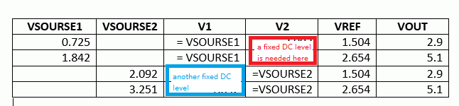
Vsource (either Vsource1 or Vsource2) is my input, and V1 or V2 is a second voltage source with fixed DC level.
When Vsource is Vsource1, we have V1 connected in the circuit. When Vsource is Vsource2, we have V2 connected in the circuit.
Let's consider the math only on my schematic, what are the values of these parameters that you think I can get the correct Vout I want?
R1
R2
Rsum1
V1
V2
RATIO
Thank you!
Sep 26, 2016
04:30 PM
- Mark as New
- Bookmark
- Subscribe
- Mute
- Subscribe to RSS Feed
- Permalink
- Notify Moderator
Please log in to access translation
Sep 26, 2016
04:30 PM
Sep 26, 2016
04:39 PM
- Mark as New
- Bookmark
- Subscribe
- Mute
- Subscribe to RSS Feed
- Permalink
- Notify Moderator
Please log in to access translation
Sep 26, 2016
04:39 PM
Thank you Alvaro. I understand your solution now, but that is not what I am looking for. What I am looking for are two fixed DC levels inside the red and blue boxes. When the input Vsource changes, these V1 or V2 are still fixed.
Sep 26, 2016
06:47 PM
- Mark as New
- Bookmark
- Subscribe
- Mute
- Subscribe to RSS Feed
- Permalink
- Notify Moderator
Please log in to access translation
Sep 26, 2016
06:47 PM
Hi Yhuang. I gues that the values that remains fixed are the four that I left blank.
Sep 27, 2016
10:00 AM
- Mark as New
- Bookmark
- Subscribe
- Mute
- Subscribe to RSS Feed
- Permalink
- Notify Moderator
Please log in to access translation
Sep 27, 2016
10:00 AM
There's a problem with your table. The amplifier gain (Vout/Vref) must be constant, but
 it's not. I suspect there's a digit transposition, because

Beyond that, the input voltage divider will not allow the voltage combinations you're specifying with the same resistors and a constant voltage on one input.
Sep 26, 2016
12:54 PM
- Mark as New
- Bookmark
- Subscribe
- Mute
- Subscribe to RSS Feed
- Permalink
- Notify Moderator
Please log in to access translation
Sep 26, 2016
12:54 PM
So you've implicitly solved the OP's problem (the six unknowns) with:
Rsum1=100 kOhm
R1=R2=75.491 kOhm
V1=2.092 V
V2=3.251 V
ratio=1.928
And provided resistor values to implement the ratio by two resistors valued 100 kOhm and 92.825 kOhm.
Luc
Sep 26, 2016
01:36 PM
- Mark as New
- Bookmark
- Subscribe
- Mute
- Subscribe to RSS Feed
- Permalink
- Notify Moderator
Please log in to access translation
Sep 26, 2016
01:36 PM
Thank you LucMeekes! Thank you for your help!
It seems like your inputs of V1 and V2 are not correct, because they are some of the input numbers of my Vsource2.
V1=2.092 V
V2=3.251 V
According to Fred's and Alvaro's results, V1=1.504V and V2=2.654V. But when I used V1=1.504V to calculate Vout when Vsource1=0.725V, the calculated result is 2.253V, instead of 2.9V. Am I missing something?
Sep 26, 2016
01:47 PM
- Mark as New
- Bookmark
- Subscribe
- Mute
- Subscribe to RSS Feed
- Permalink
- Notify Moderator
Please log in to access translation
Sep 26, 2016
01:47 PM
You're welcome.
However I find yet another solution. I suspect that my conclusion from Fred's solution is incorrect. But that would mean you'd need two different values for Rsum1.So I revisited it.
The smart thing that Fred did was take the Vsource2 as V1 in the case where Vsource1 should result in 2.9 V. And vice versa. Implicilty he not only used the same value for Rsum1 for both circuits, but also it would mean that R1=R2. But I'm afraid this may have reversed the resistive divider between both circuits.
In below analysis I have taken care that it comes out all right.

Success!
Luc
Sep 26, 2016
02:00 PM
- Mark as New
- Bookmark
- Subscribe
- Mute
- Subscribe to RSS Feed
- Permalink
- Notify Moderator
Please log in to access translation
Sep 26, 2016
02:00 PM
Thank you LucMeeks. I recalculated your results but still got some problem. Now I can use Vsource1=0.725V and V1=2.029V to get Vout=2.9V. But when I use Vsource1=1.842V and V1=2.029V, I cannot get Vout 5.1V, but Vout=3.96V. Would you advise what can go wrong?
Sep 26, 2016
04:19 PM
- Mark as New
- Bookmark
- Subscribe
- Mute
- Subscribe to RSS Feed
- Permalink
- Notify Moderator
Please log in to access translation
Sep 26, 2016
04:19 PM
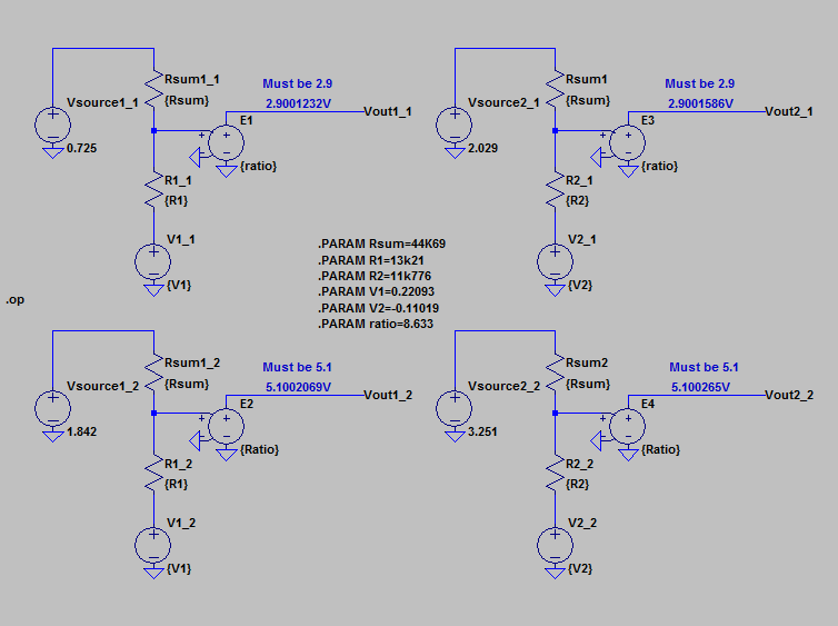
OK, So why didn't I do this right in the first place...?

To show correctness, I put the two circuits (left and right) in each of their operating modes (top and bottom) in an electronic circuit simulator (LTspice):

I think that's close enough.
Note V2= -0.0918 V, just below 0. I (again) found no solution for which V2>0.
The ratio apparently needs to be 10 (upper limit) to get as close as possible.
Success!
Luc
Sep 27, 2016
04:51 PM
- Mark as New
- Bookmark
- Subscribe
- Mute
- Subscribe to RSS Feed
- Permalink
- Notify Moderator
Please log in to access translation
Sep 27, 2016
04:51 PM
This is the solution that I found is the closest match to the requirements.
Luc
Sep 26, 2016
04:39 PM
- Mark as New
- Bookmark
- Subscribe
- Mute
- Subscribe to RSS Feed
- Permalink
- Notify Moderator
Please log in to access translation
Sep 26, 2016
04:39 PM
Note that the above is A solutio, not (yet?) THE solution.
You can get other configurations when you change guess values (Usually that's not a good sign), 'but I've not seen one where both V1 and V2 are >0, and most of the time V2 is more negative than -0.1 V.
For example:

Gives in the simulator:
Luc
PS. Attached the LTspice circuit file.
Sep 26, 2016
06:36 PM
- Mark as New
- Bookmark
- Subscribe
- Mute
- Subscribe to RSS Feed
- Permalink
- Notify Moderator
Please log in to access translation
Sep 26, 2016
06:36 PM
Hi Luc.
Haven't spice right now. But this old one it's very good (version 5.1, 1996).
Best regards.
Alvaro.
Sep 27, 2016
08:28 AM
- Mark as New
- Bookmark
- Subscribe
- Mute
- Subscribe to RSS Feed
- Permalink
- Notify Moderator
Please log in to access translation
Sep 27, 2016
08:28 AM
Hola Alvaro,
What is this program?
Sep 27, 2016
08:59 AM
- Mark as New
- Bookmark
- Subscribe
- Mute
- Subscribe to RSS Feed
- Permalink
- Notify Moderator
Please log in to access translation
Sep 27, 2016
08:59 AM
Hi Vladimir. It's a simulation program, in the original version, Electronics Workbench - Wikipedia, la enciclopedia libre .
Now it is Multisim, from National Instruments.
Best regards.
Alvaro.
Sep 27, 2016
09:14 AM
- Mark as New
- Bookmark
- Subscribe
- Mute
- Subscribe to RSS Feed
- Permalink
- Notify Moderator
Please log in to access translation
Sep 27, 2016
09:14 AM
Thank you.
Sep 27, 2016
11:55 AM
- Mark as New
- Bookmark
- Subscribe
- Mute
- Subscribe to RSS Feed
- Permalink
- Notify Moderator
Please log in to access translation
Sep 27, 2016
11:55 AM
Hi LucMeekes, can I say your conclusion is "it is not possible to find both positive V1 and V2 and all positive resistance values? Even if we use Fred/Alvaro's method?"
Sep 27, 2016
04:37 PM
- Mark as New
- Bookmark
- Subscribe
- Mute
- Subscribe to RSS Feed
- Permalink
- Notify Moderator
Please log in to access translation
Sep 27, 2016
04:37 PM
Yes, that is my conclusion given the problem description and especially the constratints you give.
Even if you allow larger values of ratio (larger than 10) I did not find a solution where V1>0 AND V2>0.
What worries me still is the fact that when I change gues values for the Given - Find block, I can get different solutions. This means there there are multiple solutions (as I've shown above), but they all have a negative V2.
Luc


