1-Visitor
September 25, 2016
Solved

How to solve this simple voltage summing circuit using Mathcad

  • September 25, 2016
  • 7 replies
  • 19102 views

Hi All, I have a simple summing circuit. Two sources  are the inputs via two resistors to generate a weighted signal Vref. Then this Vref is multiplying by a constant number "ratio" to get a Vout. The details of my circuit can be seen here:

Vsum.jpg

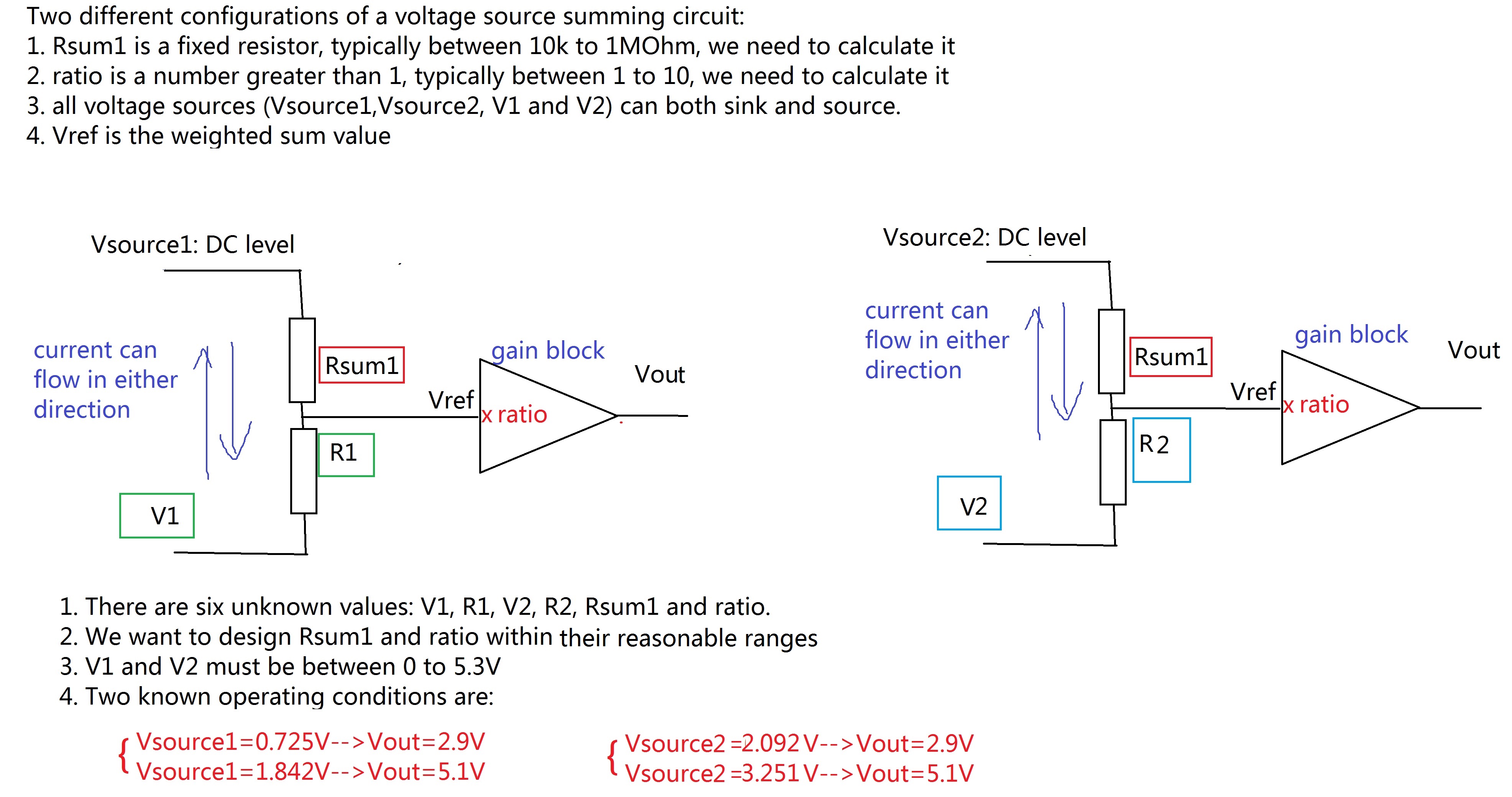
My target V1,V2 are within 0 to 5.3V, and target 10>"ratio">1, and all resistors should be between 10K to 1M ohm.  Right now I am not able to use if condition to solve the equation array to figure out what V1,V2,R1,R2 are.

I have uploaded my worksheet in the attachment. Would anyone teach me how can I calculate these values within the reasonable range, by maintaining the other two parameters "ratio" and "Rsum1" within their reasonable range? Thank you!

Best answer by LucMeekes

Yes, that is my conclusion given the problem description and especially the constratints you give.

Even if you allow larger values of ratio (larger than 10) I did not find a solution where V1>0 AND V2>0.

What worries me still is the fact that when I change gues values for the Given - Find block, I can get different solutions. This means there there are multiple solutions (as I've shown above), but they all have a negative V2.

Luc

7 replies

12-Amethyst
September 25, 2016

Hi.

For a symbolic solution, you need to convert the if statements to unitary steps.

For numeric solution you need to assign some guess values.

Theoretically, you can obtain the same solutions in both cases, but there are some issues in your equations. First, with symbolics there are a resistor with a negative value. Check the equations and try again.

Best regards.

Alvaro.

yhuang-31-VisitorAuthor
1-Visitor
September 26, 2016

Hi Alvaro, I used your worksheet and inlcuded LucMeekes' constrained conditions, now I can calculate some values. Although I have not figured out the correct solution, I still thank you for your inputs!

12-Amethyst
September 26, 2016

Hi Yhuang.

If all equations looks very similar, it's easy to make a mistake writing them.

The attached shows that selecting a ratio of 3 all the parameters are in control.

V2 is negative, but in your diagram states that current can flow in both directions, which enable any sign for the potentials.

Best regards.

Alvaro.

FIG.gif

23-Emerald IV
September 25, 2016

Here is a solution that is physically possible (all resistor values are positive), but does NOT obey the requirement V2>0.

I have not been able to find a solution that is both physically possible AND obeys the requirement that V1>0 AND V2>0.

Here's what happens when I add those constraints:

The error message here is "No solution was found..."

Success!
Luc

yhuang-31-VisitorAuthor
1-Visitor
September 26, 2016

Hi LucMeekes, thank you for your solution!

I tried to download your file but my MC14 cannot give out that physical  results you obtained.

First of all, it kept showing "This variable is undefined". It looks like the error message that F.M.‌ got is similar to what I have. Then I followed this thread (This variable is undefined error when using Given/Find function, why?) and deleted all the units.

Then it run, but kept "showing no solution was found", even if I put your solved value as my guess values. Do you know how can I solve this problem and make it run? Thank you!no solution was found .JPG

23-Emerald IV
September 26, 2016

I'm sorry, I don't know. In my Mathcad 11 it just runs; with and without units.

Is the solution with V2 being negative acceptable?

Luc

21-Topaz II
September 25, 2016

Hi yhuang-3,

Mine is a classical analytical solution obtained with the circuit inspection.

The results are listed before the solve block which had to be  used as a verify of the previous results. 

At the end, doing a test,I tried to solve the problem with a solve block but it doesn't work.

I would appreciate a lot if someonecould tell me what changes to make, so that the solve block gives a result.

Thanks so much.

Greetings

FM

Summer.jpg

25-Diamond I
September 26, 2016

You are trying to force Mathcad to display a vector consisting of different dimensions (voltage and resistance). This does not work in Mathcad 15 and below. It should work in Prime - one of the very few benefits of Prime over Mathcad.

So don't try to display the results of the Find-function but instead assign the results to a vector consisting of distinct variables.

Here are the results your solve block comes up with:

21-Topaz II
September 26, 2016

Thank you very much Werner ... you're a genius!

23-Emerald I
September 26, 2016

Recasting your problem:

12-Amethyst
September 26, 2016

Hi Fred.

Your solution it's very good.

Attached the small modifications for force it to the correct math: two equations with two unknowns.

Best regards.

Alvaro.

fig.gif

yhuang-31-VisitorAuthor
1-Visitor
September 26, 2016

Thank you Alvaro! Thank you for your help!

According to your results, V1=1.504V and V2=2.654V. But when I used V1=1.504V to calculate Vout when Vsource1=0.725V, the calculated result is 2.253V, instead of 2.9V. Am I missing something?

21-Topaz II
September 27, 2016

Hi, yhuang-3,

This is a new analysis, more simple than the ones made by me previously. However, something is wrong. The values marked red are not congruent with the other results. Who could  explain me why?

Greetings

FM

Summer.jpg

12-Amethyst
September 27, 2016

Hi F.M.

That's happen because with that selection of the parameters, you "loose information". Can't reconstruct the given values.

Even your choice looks natural, for showing the linear dependence between voltages, this other procedure it's better:

Don't choose a gain for the amplifier and make the calculus for the resistors. As physical device only can work properly into some environments. This is, can work only for some range of resistors, which are in charge to polarize it. Work with an unknown Av, and a unknown k=R1/R2. Solve for them, and after to buy the amplifier, choose one resistor and calculate the other.

Best regards.

Alvaro.

fig.gif

21-Topaz II
September 27, 2016

...... I have my own little laboratory and I have countless opamps. But having taught electronics and theoretical systems for several decades, I do not waste my time in the lab to make the circuit.

Bye

21-Topaz II
September 27, 2016

Hi Yuhang-3,  have you something to say about my last solution?

Look at what Grandpa has prepared for you. Do you like it so?

non inverting summer project.jpg

yhuang-31-VisitorAuthor
1-Visitor
September 27, 2016

Hi F.M., would you tell me how can I apply your solution to my question? In my case, the fixed DC source V1 and V2 are independent, and R1 and R2 are independent (for example, they can be connected/disconnected by a SPDT switch). But the ratio and the Rsum1 are kept the same all the time.

Thank you!

Vsum4.jpg

21-Topaz II
September 27, 2016

My dear, but how many circuits are? can you tell us? please. I have done the analysis and synthesis for a single circuit.

Your circuit is like this:

yhuang3circuit.jpg

12-Amethyst
September 27, 2016

A 'switch' have three terminals, as you show in your diagram. But in a typical voltage controlled switch, one of them is ocuppied by the controler, and only remain two terminals. And those two terminals can't act as selector, as in your diagram.

Best regards.

Alvaro.

yhuang-31-VisitorAuthor
1-Visitor
September 28, 2016

Hi Alvaro. This is just a block diagram, not the real circuit implementation. Thank you for pointing this out!