
Turn on suggestions
Auto-suggest helps you quickly narrow down your search results by suggesting possible matches as you type.
Showing results for
Please log in to access translation
Turn on suggestions
Auto-suggest helps you quickly narrow down your search results by suggesting possible matches as you type.
Showing results for
Community Tip - Need to share some code when posting a question or reply? Make sure to use the "Insert code sample" menu option. Learn more! X
- Community
- PTC Education
- PTC Education Forum
- Re: Lots of Creo Questions
Translate the entire conversation x
Please log in to access translation
Options
- Subscribe to RSS Feed
- Mark Topic as New
- Mark Topic as Read
- Float this Topic for Current User
- Bookmark
- Subscribe
- Mute
- Printer Friendly Page
Lots of Creo Questions
Mar 28, 2012
01:57 PM
- Mark as New
- Bookmark
- Subscribe
- Mute
- Subscribe to RSS Feed
- Permalink
- Notify Moderator
Please log in to access translation
Mar 28, 2012
01:57 PM
Lots of Creo Questions
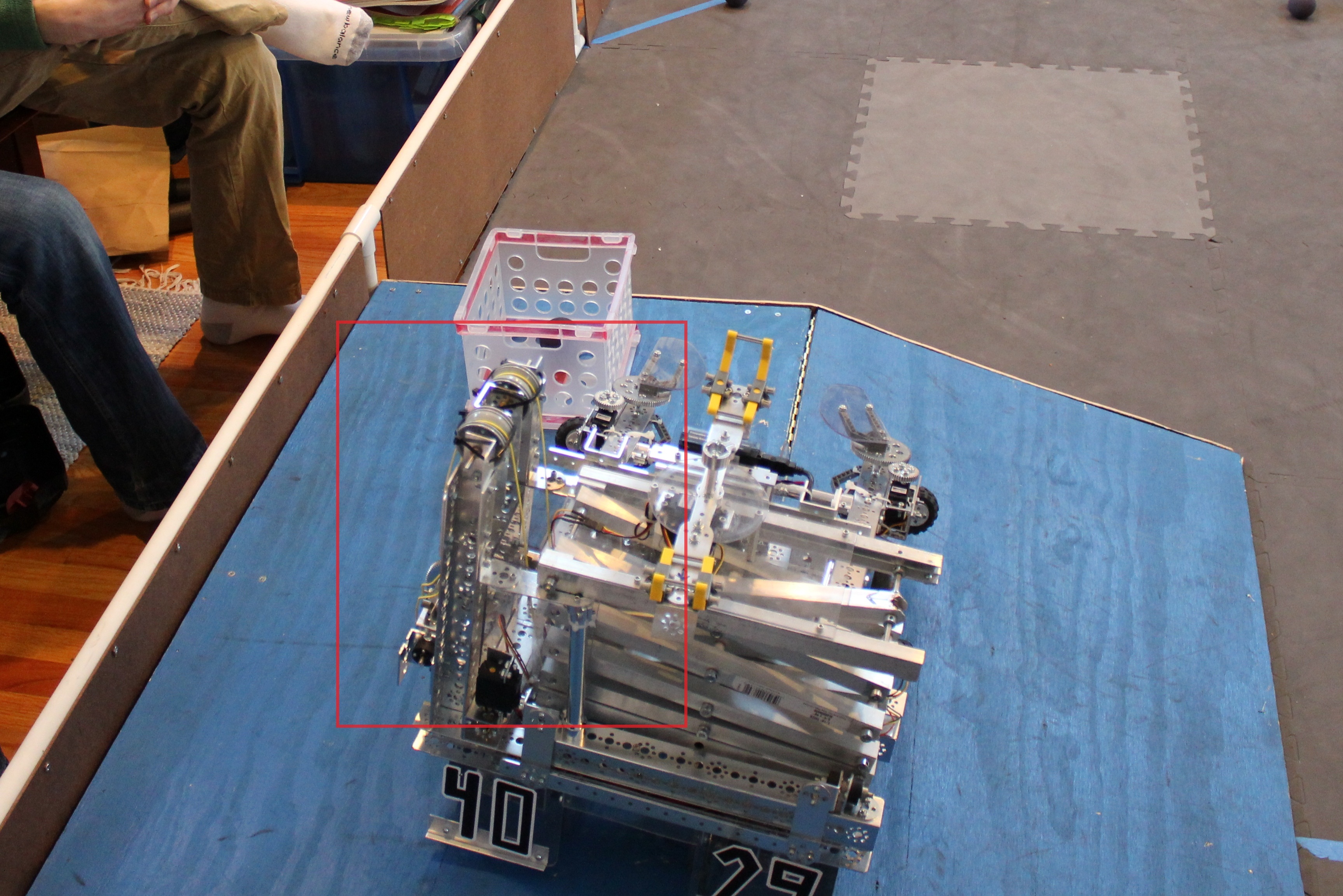
We're using Creo for our FTC team, and we're trying to get a fully functional model before Worlds. In pursuit of that, we have a bunch of questions that we're hoping people can help us address.
- How can we model a string connection in the mechanism application. Is it possible to pull a piece via string in the model? I've attached a picture to make it more clear what we're trying to do.
- Is there any way to model zip ties? Especially as far as they bend and interact with the rest of the pieces and environment?
- In our robot we have two pairs of arms. One to hold/lift the crates (crate arms) which are unpowered, and another that holds the crate arms up (holding arms). Is there any way to model how these interact in the mechanism application?
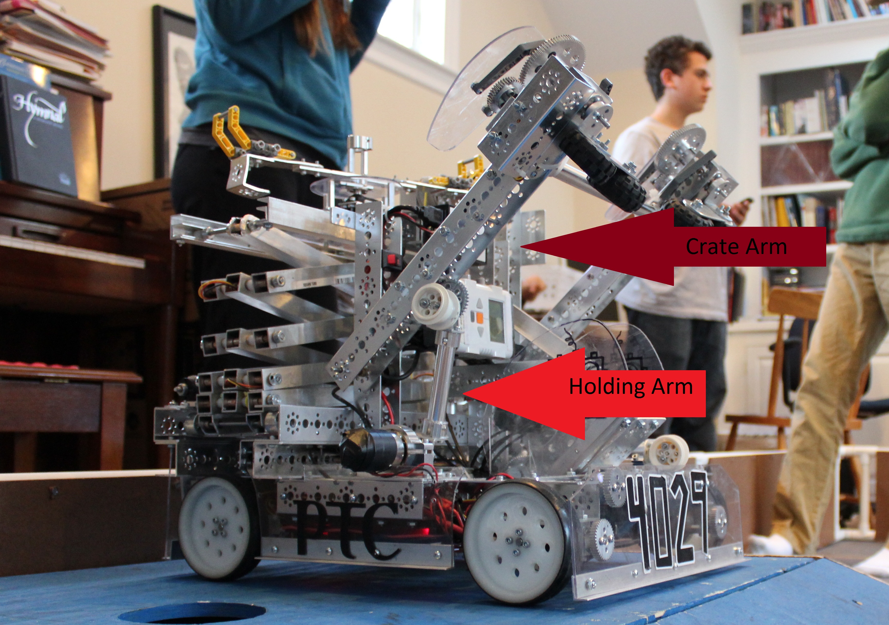
As you can see, the holding arms locks in place, preventing the crate arm from going through it.
Thanks!
Team 4029
1 REPLY 1
Mar 28, 2012
04:22 PM
- Mark as New
- Bookmark
- Subscribe
- Mute
- Subscribe to RSS Feed
- Permalink
- Notify Moderator
Please log in to access translation
Mar 28, 2012
04:22 PM
Team 4029,
Wow, you guys hae done a lot with Creo! Below are some general, theoretical answers to your questions. These are tough questions to answer without having the models and understanding your design.
1) There is not a "String" connection. You could maybe simulate this by applying a force in the direction that the string would be pulling. Another option would be to create a Sketch or curve feature representing the string. You could then create a datum point on the sketch (using the ratio option). If you assembled to that point (on the string), then when the point moves, components attached to the point would also move. This would not be a Mechanism type connection but you could move the components by editing the point, then regenerating the assembly.
2) You could model a zip tie in a number of ways, depending on your needs. Extrude the shape or create a curve (sketch or through points), then sweep the profile of the zip tie along the trajectory curve. Depending on how the part is created, you could then make it a Flexible Component to show it in different assembly states. If you used the curve through points method and the points were on different components of the assembly, the curve (trajectory of the sweep) would change as the position of the components changed.
3) I think the CAM type connection in mechanism mode would help with this.
I hope this helps!
Regards,
Adam


