
Turn on suggestions
Auto-suggest helps you quickly narrow down your search results by suggesting possible matches as you type.
Showing results for
Please log in to access translation
Turn on suggestions
Auto-suggest helps you quickly narrow down your search results by suggesting possible matches as you type.
Showing results for
Community Tip - Learn all about PTC Community Badges. Engage with PTC and see how many you can earn! X
Translate the entire conversation x
Please log in to access translation
Options
- Subscribe to RSS Feed
- Mark Topic as New
- Mark Topic as Read
- Float this Topic for Current User
- Bookmark
- Subscribe
- Mute
- Printer Friendly Page
Constant of Integration? What am I missing?
Jan 01, 2013
09:36 PM
- Mark as New
- Bookmark
- Subscribe
- Mute
- Subscribe to RSS Feed
- Permalink
- Notify Moderator
Please log in to access translation
Jan 01, 2013
09:36 PM
Constant of Integration? What am I missing?
I'm inputting some integrals that I had done by hand into Mathcad (Prime 2).
I noticed that the contants of integration are not added for symbollically integration equations, so I have been adding them. However, upon integration of one equation, I find Mathcad is inserting a constant term that falls out upon re-differentiation, and I cannot figure out where Mathcad is getting it from.
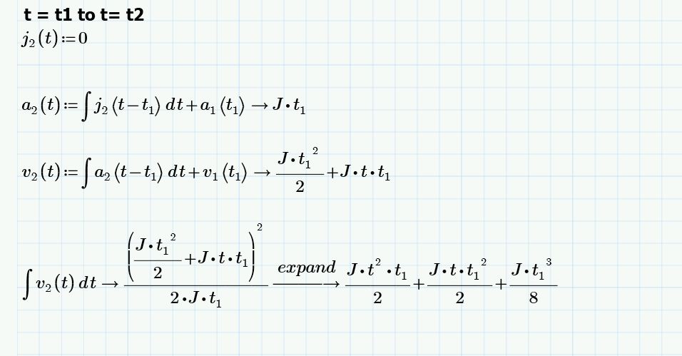
If you look at the definition for v2(t), v1(t1) is a constant term I entered manually. This term, which is supposed to represent a constant value at a point in time, correctly evaluates to 1/2 *J * t1^2 from a latter definition of v1. However, then I integrate and expand v2, I get this term which I do not get when I integrate by hand:
1/8 * J * t1^3.
When I differentiate this term falls out. Where is this coming from? Is it the constant of integration? I don't get this when I integrate by hand. Perhaps my integration is a bit rusty...I get the first 2 terms just fine.
I had initially thought that Mathcad was treating t1 like the integrated variable, but when I sbstitute the constant PI in for t1 I get the same results.
Any thoughts? I am new to Mathcad so any suggestions are appreciated. I have also included the worksheet.
For reference:
J, t1, and t2 are constant values which I was going to define later.
Thanks!
Labels:
- Labels:
-
Other
16 REPLIES 16
Jan 02, 2013
12:25 AM
- Mark as New
- Bookmark
- Subscribe
- Mute
- Subscribe to RSS Feed
- Permalink
- Notify Moderator
Please log in to access translation
Jan 02, 2013
12:25 AM
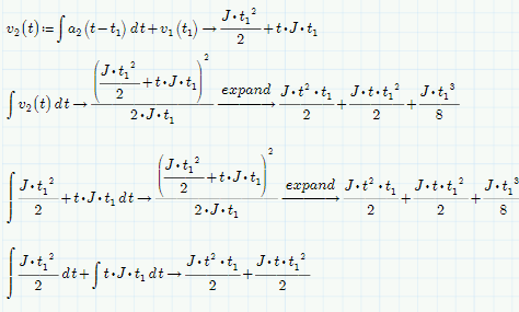
Wow, that's bizarre.... If you break it down into a summation of integrals, the extra term is (correctly) absent....
Jan 02, 2013
03:31 AM
- Mark as New
- Bookmark
- Subscribe
- Mute
- Subscribe to RSS Feed
- Permalink
- Notify Moderator
Please log in to access translation
Jan 02, 2013
03:31 AM
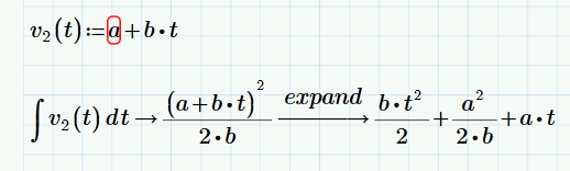
There is nothing wrong with Mathcads answer. Mathcad's symbolic quite often delivers results which are different and sometime more complex as if you would have done it by hand.
Your function v2 basically has the form a+b*t and Mathcad treats it as (a+b*t)^1 and applies the appropriate rule. Thats the reason for the adding of the constant summand a^2/(2*b) which is irritating but mathematically correct. There is no such thing as THE integral constant and therefore you cannot demand Mathcad to supply the integral without _the_ constant of integration.
BTW, is there a specific reason for chosing J as constant for j1? As you can see by the way it is displayed, Mathcad treats it as the unit Joule. Thats no problem as long as you use the symbolic processor because it knows nothing about units and treats J as a constant.
Jan 02, 2013
07:23 AM
- Mark as New
- Bookmark
- Subscribe
- Mute
- Subscribe to RSS Feed
- Permalink
- Notify Moderator
Please log in to access translation
Jan 02, 2013
07:23 AM
Does the following come close to what you are trying to achieve? I agree that its quite tedious having to add those constant summands manually.
Keep in mind that the indefinite Integral is not always necessarily the same as the integral from 0 to t!

Jan 02, 2013
11:09 AM
- Mark as New
- Bookmark
- Subscribe
- Mute
- Subscribe to RSS Feed
- Permalink
- Notify Moderator
Please log in to access translation
Jan 02, 2013
11:09 AM
Thanks Werner, the latter example is closer to what I am trying to acheive.
I will substitute J with another variable name to prevent confusion with Joule and refrain from using variations of t.
Some back story in case you are interested:
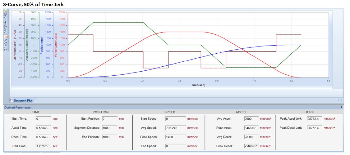
The equations (if you haven't deduced) are for Jerk (rate of change of Acceleration), Acceleration, Velocity, and Displacement. We have a vendor that produces motion servo drives and have supplied from (murky) documentation regarding the equations they use for a trapezoidal acceleration profile (thus a piecewise function across 3 sub-regions: 0 to t1, t1 to t2, and t2 to t3). The amount of time that the end regions (regions where acceleration is changing and Jerk is non-zero) can vary depending on how smooth one would like the movement to be.
Specifying Jerk to occur 100% of time will result in a triangular profile (where t1 = t2, and there is no middle sub-region).
The vendor supplied an equation that supposedly gives the Jerk the servo drives come up with based on the Acceleration, Velocity, and % of the total time Jerk is supplied (0 to t1, and t2 to t3), however upon investigation I determined the equation they supplied is non consistant with what is actually occurring. I managed to correct their equation but I want to derive it myself for documentation purposes, and also have a better understanding of the effect of changing certain parameters.
Thanks for the help and clarification.
Jan 02, 2013
02:26 PM
- Mark as New
- Bookmark
- Subscribe
- Mute
- Subscribe to RSS Feed
- Permalink
- Notify Moderator
Please log in to access translation
Jan 02, 2013
04:10 PM
- Mark as New
- Bookmark
- Subscribe
- Mute
- Subscribe to RSS Feed
- Permalink
- Notify Moderator
Please log in to access translation
Jan 02, 2013
04:10 PM
Thanks WE, definitely helpful.
Unfortunantely the solution isn't as simple as being able to specify the regions of time.
The input the motion servo takes is:
Peak Velocity
Average Acceleration
% of time Jerk is non-zero, where % of time is:
( t1 + (t3 - t2) ) / t3 ) * 100
Also, J3 = - J1
From that info everything as a function of time is calculated.
The equation I am trying to derive is the following:
J1 = ( (Average Accel) ^2 / Peak Velocity ) * ( (200/ % of Time) - 1).
Here is a screenshot of my motion analyzer program just to give you an idea of what I am looking at. Unfortunately I can't look at the math behind it. The data in my spreadsheet suppled only is for the fist half of the displacement.
Jan 02, 2013
04:49 PM
- Mark as New
- Bookmark
- Subscribe
- Mute
- Subscribe to RSS Feed
- Permalink
- Notify Moderator
Please log in to access translation
Jan 02, 2013
04:49 PM
So, if, as I assume, v(t3) should be zero again and with J3=-J1 there must be some symmetry, that is t2=t3-t1, right?
Average acc. is
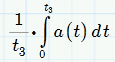
or RMS
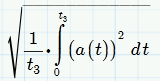
.
Jan 02, 2013
04:57 PM
- Mark as New
- Bookmark
- Subscribe
- Mute
- Subscribe to RSS Feed
- Permalink
- Notify Moderator
Please log in to access translation
Jan 02, 2013
04:57 PM
Yes, the Accel profile should be symmetrical about X = (t1+t3 / 2)
For average accel we want the arethmetic mean and not RMS.
Jan 02, 2013
06:16 PM
- Mark as New
- Bookmark
- Subscribe
- Mute
- Subscribe to RSS Feed
- Permalink
- Notify Moderator
Please log in to access translation
Jan 02, 2013
06:16 PM
Kris Cui schrieb:
Yes, the Accel profile should be symmetrical about X = (t1+t3 / 2)
For average accel we want the arethmetic mean and not RMS.
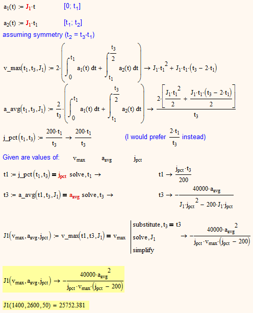
The symmetry is around t3 / 2, isn't it?
Assuming this, I got another formula than the one you are striving for, but the value from your screenshot seems to fit, as far as I can see.
I wrote it in Mathcad 15 as Prime is reacting so slow on my machine - it doesn't make fun to work with. I converted it to Prime-format and it seems to work. I attach both files.
WE
Jan 02, 2013
06:45 PM
- Mark as New
- Bookmark
- Subscribe
- Mute
- Subscribe to RSS Feed
- Permalink
- Notify Moderator
Please log in to access translation
Jan 02, 2013
06:45 PM
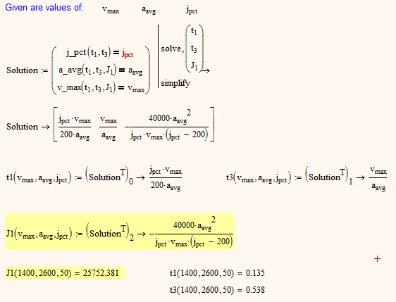
Just got the idea for a better method for solving that system of three equations.
The time values (t1 and t3) calculated seem to fit the ones in your screenshot, too.
Jan 02, 2013
07:10 PM
- Mark as New
- Bookmark
- Subscribe
- Mute
- Subscribe to RSS Feed
- Permalink
- Notify Moderator
Please log in to access translation
Jan 02, 2013
07:10 PM
I just realized that in my foregoing calculations I missed the fact that according to your screenshot there is (beginning at t3) a time of zero acceleration (from about 0.55 to 0.75). This does not affect v_max and a_avg but I assume it affects j_pct. The percentage is taken from which time? I guess from t4 which is around 0.56 s in the screenshot. It would mean that we have a fourth variable t4 but still only 3 equations!
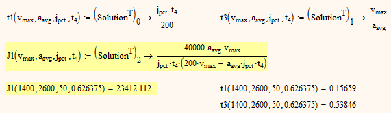
If t4 (the center of the zero acceleration phase between accel and decel) is an additional value you can provide along with v_max, a_avg and j_pct, you get
Jan 02, 2013
02:51 PM
- Mark as New
- Bookmark
- Subscribe
- Mute
- Subscribe to RSS Feed
- Permalink
- Notify Moderator
Please log in to access translation
Jan 02, 2013
02:51 PM
If you don't insist in symbolic evaluation you may try the attached
Jan 03, 2013
07:40 PM
- Mark as New
- Bookmark
- Subscribe
- Mute
- Subscribe to RSS Feed
- Permalink
- Notify Moderator
Please log in to access translation
Jan 03, 2013
07:40 PM
Kris, are you still out there?
I had a closer look at your screenshot and it seems, that the percentage Time of Jerk is taken in relation to the total amount of acceleration (without the time of zero accel in the middle).
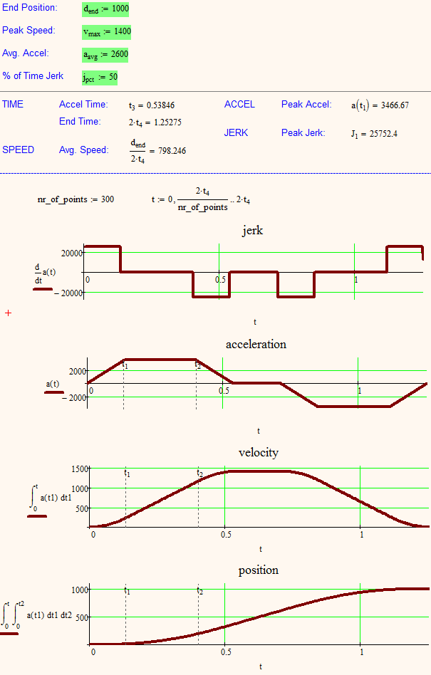
I have refined my worksheet, added the input of the end position to calculate the time of constant velocity in the center of the segment and as you can see, all the values calculated fit more than perfect compared to those in your screenshot.
So the equation for J1 you had in mind has to be multiplied by (1 - percentage / 200)^(-2) to get the correct results.
Jan 03, 2013
09:30 PM
- Mark as New
- Bookmark
- Subscribe
- Mute
- Subscribe to RSS Feed
- Permalink
- Notify Moderator
Please log in to access translation
Jan 03, 2013
09:30 PM
Werner,
Sorry, wasn't ignoring you! Tied up the past couple days on other issues. That looks spot on. I actually had some free-time to spend on my worksheet today and came up with similar results, which gives me a bit of a confidence booster.
Would you be able to post your modified worksheet?
Thanks for the help.
Kris
Jan 03, 2013
10:15 PM
- Mark as New
- Bookmark
- Subscribe
- Mute
- Subscribe to RSS Feed
- Permalink
- Notify Moderator
Please log in to access translation
Jan 03, 2013
10:15 PM
Would you be able to post your modified worksheet?
Sure - here you are.
Jan 04, 2013
08:49 AM
- Mark as New
- Bookmark
- Subscribe
- Mute
- Subscribe to RSS Feed
- Permalink
- Notify Moderator
Please log in to access translation
Jan 04, 2013
08:49 AM
Sorry, I forgot to convert in Prime format. I don't know if you have MC 15 installed.
Find it attached.
BTW, you can use units in the sheet without any change. Mathcad changes units in the result, e.g to m/s and you have to redo it manually. Especially the graphs would need some work (multiplying the ordinate function and the limit by 1000).
I just see that the converted Prime version seems not to work. The symbolic solve finds no solution. Thats strange as both MC15 and Prime2 use the same (third party) symbol engine. Hope its of help nevertheless. I include a pdf print of the MC15 version so you see how it's supposed to look.
Correction: I have rewritten one of the expressions and now it seems to work in Prime, too.
That expression was inserted by the converter as a picture, not an expression. Strange. I have rewritten that expression in MC15, too, and it went from all red to black. It was the expression just before the solve
Increasing nr_of_points to 300 or more gets you a "real" square wave for the jerk graph, but the position graph will then take quite some time to calculate.
I justed noticed: Prime files really pack small when zipped!


