Turn on suggestions
Auto-suggest helps you quickly narrow down your search results by suggesting possible matches as you type.
Showing results for
Please log in to access translation
Turn on suggestions
Auto-suggest helps you quickly narrow down your search results by suggesting possible matches as you type.
Showing results for
Community Tip - Want the oppurtunity to discuss enhancements to PTC products? Join a working group! X
- Community
- Customer Success
- PTC University Training
- Re: Top Down Design - Bearings
Translate the entire conversation x
Please log in to access translation
Options
- Subscribe to RSS Feed
- Mark Topic as New
- Mark Topic as Read
- Float this Topic for Current User
- Bookmark
- Subscribe
- Mute
- Printer Friendly Page
Top Down Design - Bearings
Jul 08, 2014
03:35 PM
- Mark as New
- Bookmark
- Subscribe
- Mute
- Subscribe to RSS Feed
- Permalink
- Notify Moderator
Please log in to access translation
Jul 08, 2014
03:35 PM
Top Down Design - Bearings
Using motion skeletons to attempt to completely animate a worm gear. All parts are already modelded top down, and the motion skeleton is complete. Problem is, I cannot figure out how to get the balls and carrier to rotate correctly (rolling along the track). The ratio of turns from the inside to the bearing carrier is a function of the diameters, and figuring out the ratio will be simple, but I'm having trouble on the actual creation of the Skeleton body. If anyone knows how to do this, or knows of a tutorial, it would be great.
Solved! Go to Solution.
ACCEPTED SOLUTION
Accepted Solutions
Jul 09, 2014
10:11 AM
- Mark as New
- Bookmark
- Subscribe
- Mute
- Subscribe to RSS Feed
- Permalink
- Notify Moderator
Please log in to access translation
Jul 09, 2014
10:11 AM
It's essentially an epicyclic gear.
If the outer race is stationary, and the inner race is rotating (planetary epicyclic: sun in, carrier out, annulus grounded), then the ratio between the inner ring speed and the cage (carrier) speed is [R+1]:1 where R is [outer race contact dia ÷ inner race contact dia].
6 REPLIES 6
Jul 08, 2014
06:42 PM
- Mark as New
- Bookmark
- Subscribe
- Mute
- Subscribe to RSS Feed
- Permalink
- Notify Moderator
Please log in to access translation
Jul 08, 2014
06:42 PM
The "floating balls" needs a carrier. It is similar to sun gears but you also have a linear component that needs to be programmed into the motion.
Typically people do not show the rotation of the balls but it can be done...
Jul 09, 2014
09:34 AM
- Mark as New
- Bookmark
- Subscribe
- Mute
- Subscribe to RSS Feed
- Permalink
- Notify Moderator
Please log in to access translation
Jul 09, 2014
09:34 AM
This seems to be what I want to do, but it only shows how to check the links to verify the balls are turning correctly against the carrier. Is there a way to to this with a motion skeleton, or will I be relegated to trying to make it work with mechanism? I don't specifically need the balls to roll, just the carrier and the balls to move. What I think would work is to setup the balls and carrier as their own assembly, then instead of assembling a bearing in, assemble the inner, outer, and carrier/ball pieces. That way (with the motion skeleton), the planes that they are assigned to will rotate independently, and therefore, the inner race and ball/carrier combo will also rotate independently.
The question now is, what is the turn ratio for the carrier itself instead of the bearing's balls.
Jul 09, 2014
10:11 AM
- Mark as New
- Bookmark
- Subscribe
- Mute
- Subscribe to RSS Feed
- Permalink
- Notify Moderator
Please log in to access translation
Jul 09, 2014
10:11 AM
It's essentially an epicyclic gear.
If the outer race is stationary, and the inner race is rotating (planetary epicyclic: sun in, carrier out, annulus grounded), then the ratio between the inner ring speed and the cage (carrier) speed is [R+1]:1 where R is [outer race contact dia ÷ inner race contact dia].
Jul 09, 2014
11:31 AM
- Mark as New
- Bookmark
- Subscribe
- Mute
- Subscribe to RSS Feed
- Permalink
- Notify Moderator
Please log in to access translation
Jul 09, 2014
11:31 AM
I hadn't thought to allow the contact diameters as pitch diameters like that, which was a lousy mental excercise on my part. That makes a lot of sense though, and thank you for the help.
Jul 09, 2014
10:06 AM
- Mark as New
- Bookmark
- Subscribe
- Mute
- Subscribe to RSS Feed
- Permalink
- Notify Moderator
Please log in to access translation
Jul 09, 2014
10:06 AM
As a reference, I'll attach an image of the exploded bearing I have thus far.
It's a quick and dirty explode, but it will do the trick. The balls are individual, and patterned around the center axis in the assembly. I'm thinking the Ring carriers, balls, and pins would go into their own assembly, then assign those to another gear pair off the original driving worm. Multiply the reduction from inner race to carrier by the reduction of the original worm. Thoughts?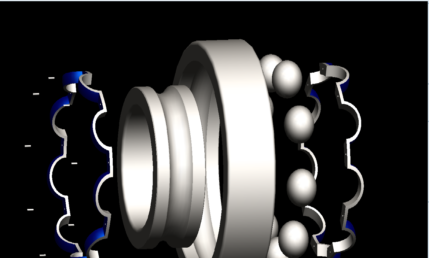
Jul 09, 2014
12:10 PM
- Mark as New
- Bookmark
- Subscribe
- Mute
- Subscribe to RSS Feed
- Permalink
- Notify Moderator
Please log in to access translation
Jul 09, 2014
12:10 PM
I have done this with planetary gears as well.
This is a great site for calculating this with gear teeth but you can subsitute perimeters (circumference)
http://www.torcbrain.de/uebersetzungsrechner-planetengetriebe/?lang=en
Search Epicycle Gear Calculator in Google will turn up quite a few great links.
In my original bearing, I also did the mental excersize to get it clear in my mind.
Somehow I was thinking you were doing a leadscrew