
Turn on suggestions
Auto-suggest helps you quickly narrow down your search results by suggesting possible matches as you type.
Showing results for
Please log in to access translation
Turn on suggestions
Auto-suggest helps you quickly narrow down your search results by suggesting possible matches as you type.
Showing results for
Community Tip - Need to share some code when posting a question or reply? Make sure to use the "Insert code sample" menu option. Learn more! X
- Community
- Creo+ and Creo Parametric
- Routed Systems
- Re: creo schematic symbols
Translate the entire conversation x
Please log in to access translation
Options
- Subscribe to RSS Feed
- Mark Topic as New
- Mark Topic as Read
- Float this Topic for Current User
- Bookmark
- Subscribe
- Mute
- Printer Friendly Page
creo schematic symbols
May 26, 2021
01:47 PM
- Mark as New
- Bookmark
- Subscribe
- Mute
- Subscribe to RSS Feed
- Permalink
- Notify Moderator
Please log in to access translation
May 26, 2021
01:47 PM
creo schematic symbols
getting started on creo schematics after having used pro/diagram,.
I"m finding there are not any connector symbols or an easy way to create them.
this is unreal for such an expensive product.
can anyone direct me to how to easily create multi port connector symbols.
it's sad that something this basic is missing.
thanks much,
Labels:
- Labels:
-
Creo Schematics
18 REPLIES 18
May 26, 2021
02:17 PM
- Mark as New
- Bookmark
- Subscribe
- Mute
- Subscribe to RSS Feed
- Permalink
- Notify Moderator
Please log in to access translation
May 26, 2021
02:17 PM
Schematics is extremely flexible but unfortunately, it also leaves a lot to the user to decide what they want and how to make it like they want.
There are tutorials on the PTC web site created by the former product manager.
It is easiest to make the connector(s) shape a variable item. That lets you create a center section that is repeated as many times as you need sandwiched between top and bottom shapes.
Make a port that works with your connector shape and place it in the center section.
Our port looks like 
We made our connectors to be plain rectangular boxes. Some people use rounded corners or other identifiers to show plugs vs sockets, we didn't.
We also designed our components with the connectors in them. It takes more work to set up the data but when someone places a component, the correct connector is already there instead of needing to be looked up.

The thin outline is our connector shape. It has four sides but one is covered up when part of a symbol.
A variable length connector starts with all the ports on one side and evenly spaced.
When you use it as part of a symbol or place it separately in your design, you can change the spacing, change to order, and split into multiple pieces.
May 26, 2021
04:48 PM
- Mark as New
- Bookmark
- Subscribe
- Mute
- Subscribe to RSS Feed
- Permalink
- Notify Moderator
Please log in to access translation
May 26, 2021
04:48 PM
Thank you very much for the reply,
please let me know which command tool I need to go to to create a port and a shape?
I'm totally lost in the command ribbon, nothing seems to lead to shape creation,
I appreciate the information.
I'm still stumped that there isn't a library of symbols that can be easily modified.
thanks again.
May 27, 2021
04:53 AM
- Mark as New
- Bookmark
- Subscribe
- Mute
- Subscribe to RSS Feed
- Permalink
- Notify Moderator
Please log in to access translation
May 27, 2021
04:53 AM
Hi ,
I think Creo Schematics has good help on this , please check following :
- topic in help center :" "To Create a Variable Group" "
- topic in Basic Tutorial :"Creo Schematics 7.0.0.0 Basic Tutorial > Configuring the Work Environment > Configuring a Variable Connector"
- in addition , you can always use the Sample Catalog as start (you can find it in Get Started tab) , it already include variety of connector .
- other option is to buy Component Libraries from Virtual Interconnect
Regards,
Gaby
May 27, 2021
10:02 AM
- Mark as New
- Bookmark
- Subscribe
- Mute
- Subscribe to RSS Feed
- Permalink
- Notify Moderator
Please log in to access translation
May 27, 2021
10:02 AM
Thank you for this information,
however I cannot find "artifacts properties" anywhere in creo schematics,
the catalog explorer group, I can create a new group, it has "internal_len", but does not have "obj_type", once I create the group, I can't place it,
I basically want a rectangle with 3, 6, 12, 32 ports/nodes, etc....I haven't had any training but I can't believe it's this difficult for such a basic thing...thanks so much.
May 27, 2021
10:02 AM
- Mark as New
- Bookmark
- Subscribe
- Mute
- Subscribe to RSS Feed
- Permalink
- Notify Moderator
Please log in to access translation
May 27, 2021
10:02 AM
yes I have the sample catalog, it has nothing I can use or modify it seems.
May 27, 2021
12:44 PM
- Mark as New
- Bookmark
- Subscribe
- Mute
- Subscribe to RSS Feed
- Permalink
- Notify Moderator
Please log in to access translation
May 27, 2021
12:44 PM
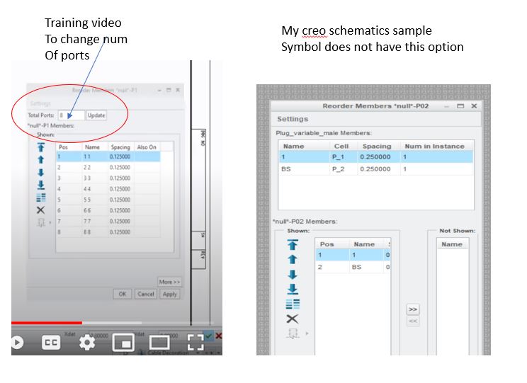
in a instructional video, it shows how to change the number of ports in placing a sample symbol,
my creo schematics does not have this option.
any thoughts?
see attached image.
May 28, 2021
09:06 AM
- Mark as New
- Bookmark
- Subscribe
- Mute
- Subscribe to RSS Feed
- Permalink
- Notify Moderator
Please log in to access translation
May 28, 2021
09:06 AM
After talking with my co-workers we might have to purchase the symbols library, this is nothing short of ridiculous, it's like buying a car and then having to return to the dealership to buy the transmission!!!!, Pro/diagram worked great, PTC must have hired the guys who invented new coke to abandoned pro/diagram and develop the cumbersome RSD/Creo schemtics to sell as a stand alone schematic platform. terrible business move, I know it's cost them some major schematic clients, CNH, Komatsu, John Deere, Harley Davidson to name four,...thanks for all the advice, it just doesn't appear that I can even make my own symbols without the library.
KMH
May 28, 2021
09:46 AM
- Mark as New
- Bookmark
- Subscribe
- Mute
- Subscribe to RSS Feed
- Permalink
- Notify Moderator
Please log in to access translation
May 28, 2021
09:46 AM
I will be answering some of your other questions in a post I have been working on.
You DO NOT need to buy a library. We looked at a library from a very knowledgeable vendor and decided it would not help us. It contained primitives for a lot of items from the European standard. Even if we used that style of design, I looked at what they were and the work needed to make them into complete components (group shapes in PTC) and realized that making our own primitives (coil, lamp, LED, relay contact, switch contacts, motor pump, and common multiple items like our most common switches) would work better and easier to combine. I have a building blocks sheet on a librarian (aka password protected) design that has them. The building blocks sheet is also a great place to build up and check anew component's design before creating the group shape.
I have three designs of this one that I showed the users . The switch sections are aimed in opposite directions but that was wanted. We usually made components with source on the left and output on the right but that got ugly very quickly. Most of my items were done by tracing over the primitives with one connected line so that items with spatial requirements like the switch at the bottom. It makes it easier to move things around.
Your schematic symbols are very company or group specific. If they included a library, it would likely require your company to change what your designs look like (still possible but the library we created would not take any new training for the homneowners and service technicians that have seen our old ones.
Our designs and symbols look vastly different than the major aerospace and heavy equipment companies I have seen. We use a style and symbols that are more like most automotive diagrams I have seen, but each corporation in that field has slightly different symbols.
May 28, 2021
11:26 AM
- Mark as New
- Bookmark
- Subscribe
- Mute
- Subscribe to RSS Feed
- Permalink
- Notify Moderator
Please log in to access translation
May 28, 2021
11:26 AM
I have been assuming that you are using the full version of Schematics instead of the light version. The light version has a lot of limitations, including not allowing use of a library. You can create items in a design but they are only for that design.
Those of us answering have been forgetting to mention that many of the tutorial videos were made with Version 3 but that should not affect this. I have used the term "previous product manager" a few times. He retired about the time Covid hit and PTC didn't get a new product manager on board until recently. He has a long history with the Schematics team but is just getting his feet on the ground with regards to having the whole picture. The newer versions were primarily problem fixes and people are hoping for some bigger changes in the next version.
When you place a variable connector you should see (we are using Schematics 4, no major changes in the newer ones yet) something like:
[cid:image001.png@01D753A4.838DCFD0]
The bottom icon on the group at the right is place.
[cid:image002.png@01D753A4.838DCFD0]
You must use the Total Ports box at the top and click on update or it does not accept the change.
The placement image will not change until you also click on apply. You can place connectors at any time with the present settings.
[cid:image003.png@01D753A6.7E3862A0]
The spacing is between the item selected and the one under it on the list.
You can change individual spacing, order, or hide items. The More>> button shows you hidden items.
The arrow by the connector, shows the direction of the ports.
If you right click on the connector that you have placed, you can select copy then Paste Shapes to make a copy of the connector with the same ID. If you just use paste, it creates a new connector with a different ID.
The copies with the same ID are the same connector. You can hide terminals in each copy. If you leave two of the same terminal in place, the Also On column will warn you that you have two copies.
May 28, 2021
01:48 PM
- Mark as New
- Bookmark
- Subscribe
- Mute
- Subscribe to RSS Feed
- Permalink
- Notify Moderator
Please log in to access translation
May 28, 2021
01:48 PM
Thus is the problem, if you can see my attached image here,
I don't have the option for "total ports", it just isn't here,
I assume I have the full version of creo schematics, I hadn't heard of a light version.
thanks tho.
May 28, 2021
03:02 PM
- Mark as New
- Bookmark
- Subscribe
- Mute
- Subscribe to RSS Feed
- Permalink
- Notify Moderator
Please log in to access translation
May 28, 2021
03:02 PM
I missed your image and see that mine did not show up. I will try to attach them.
Duh! I should have known you have the full version. You talked about the cost. Light version is free but only good enough to do some simple testing.
I should have asked which version of Schematics you have. (should be able to be found in File -> Help -> About...)
Your Reorder Members window is very different from mine. Hopefully you can see this image.

Does your connector groupshape look something like this, with the dashed lines in the Groupshape?

The dashed lines are part of a variable component. They have to be very specifically created or they don't work. For some reason the middle part is inverted. That connector has the port number ABOVE the port when it is placed.

May 28, 2021
11:43 AM
- Mark as New
- Bookmark
- Subscribe
- Mute
- Subscribe to RSS Feed
- Permalink
- Notify Moderator
Please log in to access translation
May 28, 2021
11:43 AM
Hi KH...
The people responding here are giving you good advice. I know firsthand how difficult it can be to adopt Creo Schematics. I have performed many installations and developed libraries for several companies in the past as part of my consulting business.
Everyone is trying to help by pointing you to more tutorials and documents which, in my humble opinion, are just as confusing as the help files. By the time you decipher everything, you'll be so frustrated you'll wonder why you started down this path in the first place!
So... how about this... let me know your availability and we can set up a series of conference calls (WebEx, GoToMeeting, Teams, Zoom, whatever) and I will work with you to get you oriented and moving in the right direction. I can also throw some libraries your way including ones for some common Mil spec connectors.
Recently I lost a bid to do this kind of work under contract with a company. IMHO, they made a poor decision save a few hundred dollars in hopes that everyone else providing this kind of service cares whether they are successful or not. So... you're in luck! I'm annoyed at not being chosen so I will simply help you for free for as long as you need. Don't try to understand my logic, LOL... it only makes sense to me.
If you wish, write back in private with a good contact email or phone number. I'll send you my contact information, too and we can work together offline to get you up to speed quickly.
Thanks!!
-Brian
PS: To anyone else having difficulty setting up Creo Cabling, Creo Schematics, or Creo Piping (including Spec-Driven Piping)... simply introduce yourself and I'll do my best to help if I can.
May 28, 2021
01:52 PM
- Mark as New
- Bookmark
- Subscribe
- Mute
- Subscribe to RSS Feed
- Permalink
- Notify Moderator
Please log in to access translation
May 28, 2021
01:52 PM
thanks, my obvious question is, instead of developing libraries for companies, why isn't a very basic symbol library included within creo schematics to start with ?,
it's expensive software and basically useless from the start unless you have symbols,
just basic symbols that can easily be modified would mean everything!
I'm still discussing it with my team.
(pro/diagram was still much easier to use and worked just fine IMHO) 🙂
thank you very much tho!
May 28, 2021
02:47 PM
- Mark as New
- Bookmark
- Subscribe
- Mute
- Subscribe to RSS Feed
- Permalink
- Notify Moderator
Please log in to access translation
May 28, 2021
02:47 PM
A very basic library would not be significantly useful. Just too much variation in styles. It is actually easier to build up symbols from scratch than to edit simple ones.
If you want to contact me off line, I can send you a couple things to get you started.
Bill dot fuhrmann at toro.com
May 28, 2021
02:52 PM
- Mark as New
- Bookmark
- Subscribe
- Mute
- Subscribe to RSS Feed
- Permalink
- Notify Moderator
Please log in to access translation
May 28, 2021
02:52 PM
it would be useful to me, I just need symbols to represent harness connectors, 3, 4, 6, 8, 32, 48 pins, I'd like a simple connector, in rectangular shape with 32 ports/nodes....I call that simple, but unfortunately my creo schematics does not let me create one and does not have one readily available., I've seen lots of instructional videos for creo schematics whereas they always already have their library, so no help there, I've seen the video where they can change their port numbers on the sample variable symbol for what they need, that would work for except my creo schematics does not give me that option, I'm render unproductive for now.
thanks again, have a great holiday weekend.
Jun 02, 2021
09:53 PM
- Mark as New
- Bookmark
- Subscribe
- Mute
- Subscribe to RSS Feed
- Permalink
- Notify Moderator
Please log in to access translation
Jun 02, 2021
09:53 PM
Hi KH...
I think with a call on Microsoft Teams or GoToMeeting I could get you back to work. Once you have a basic library functioning for your organization, I think you'll be successful with Creo Schematics. Please feel free to reach out. I'll work within your schedule to help.
Thanks!
-Brian
Jun 04, 2021
11:37 AM
- Mark as New
- Bookmark
- Subscribe
- Mute
- Subscribe to RSS Feed
- Permalink
- Notify Moderator
Please log in to access translation
Jun 04, 2021
11:37 AM
Thank you, I appreciate the offer,
in the past few days I have found the magic click button
to add ports to a symbol, it's well hidden and didn't look like any one else's window.
obviously everything in creo schematics has to be set up before hand,
this is very time consuming and confusing.
we are considering using spreadsheets and forgoing schematics all together,
it doesn't seem worth the time and effort just for an image, we can generate the logical info
from a spreadsheet.
I have a hard time believing PTC abandoned Pro/diagram for creo schematics, it's just very cumbersome and not intuitive in anyway.
I appreciate all the advice.
Thank You.
KMH
Jan 24, 2023
11:53 AM
- Mark as New
- Bookmark
- Subscribe
- Mute
- Subscribe to RSS Feed
- Permalink
- Notify Moderator
Please log in to access translation
Jan 24, 2023
11:53 AM
Hi Brian, I can really use some general help. I completed a course with PTC on RSD back 10 years ago and now that we no longer have Creo Diagram, we are forced to use Creo Schematics. I am running into problems like not knowing the simple task of setting up the REF_DES. It is now called "Full_Name?" I so confused since every schematic and even when I used to drawing on paper with a pencil, we called our symbols "REFERENCE DESIGNATORS." Using Creo Parametric terminology, how do I make a relation in Creo Schematics where "REF_DES" = "FULL_NAME"? All of our legacy diagrams are created with the REF_DES parameter and it wasn't until we exported some of our diagrams did we come to realize that the Full_Name is the name of the symbol. That is not correct for we used the symbol multiple times and all our reference designators now needed to be fixed becuase the names are not UNIQUE. I am looking for any resource that can help me, how can I contact you. Where can I find your email so that I can reach out to you?
Announcements


Top Tags
