
Turn on suggestions
Auto-suggest helps you quickly narrow down your search results by suggesting possible matches as you type.
Showing results for
Please log in to access translation
Turn on suggestions
Auto-suggest helps you quickly narrow down your search results by suggesting possible matches as you type.
Showing results for
Community Tip - You can subscribe to a forum, label or individual post and receive email notifications when someone posts a new topic or reply. Learn more! X
- Community
- Creo+ and Creo Parametric
- System Administration, Installation, and Licensing topics
- Re: Parameter not defined
Translate the entire conversation x
Please log in to access translation
Options
- Subscribe to RSS Feed
- Mark Topic as New
- Mark Topic as Read
- Float this Topic for Current User
- Bookmark
- Subscribe
- Mute
- Printer Friendly Page
Parameter not defined
Mar 17, 2017
06:28 AM
- Mark as New
- Bookmark
- Subscribe
- Mute
- Subscribe to RSS Feed
- Permalink
- Notify Moderator
Please log in to access translation
Mar 17, 2017
06:28 AM
Parameter not defined
Hello,
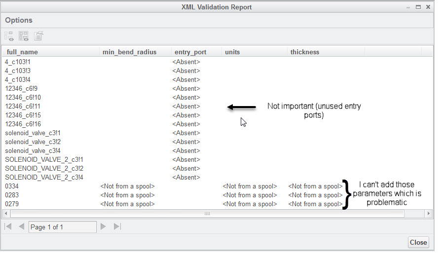
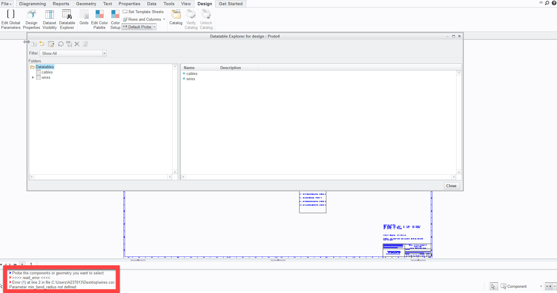
I am trying to affect a spool to a wire and in order to do this i need to import a datatable (I use Creo-schematics 3.0)
The problem is that i get an error msg saying that parameter min_bend_radius is not defined
When i try to directly edit the fiber I also can't add this parameter (as well as others : color, ..)
I think it might be a configuration error I made but i didn't find a way to manage it
Images below to illustrate:
Thank you for your help
Ambroise.
Solved! Go to Solution.
Labels:
- Labels:
-
General
- Tags:
- schematics
- spool
ACCEPTED SOLUTION
Accepted Solutions
Mar 20, 2017
09:51 AM
- Mark as New
- Bookmark
- Subscribe
- Mute
- Subscribe to RSS Feed
- Permalink
- Notify Moderator
Please log in to access translation
Mar 20, 2017
09:51 AM
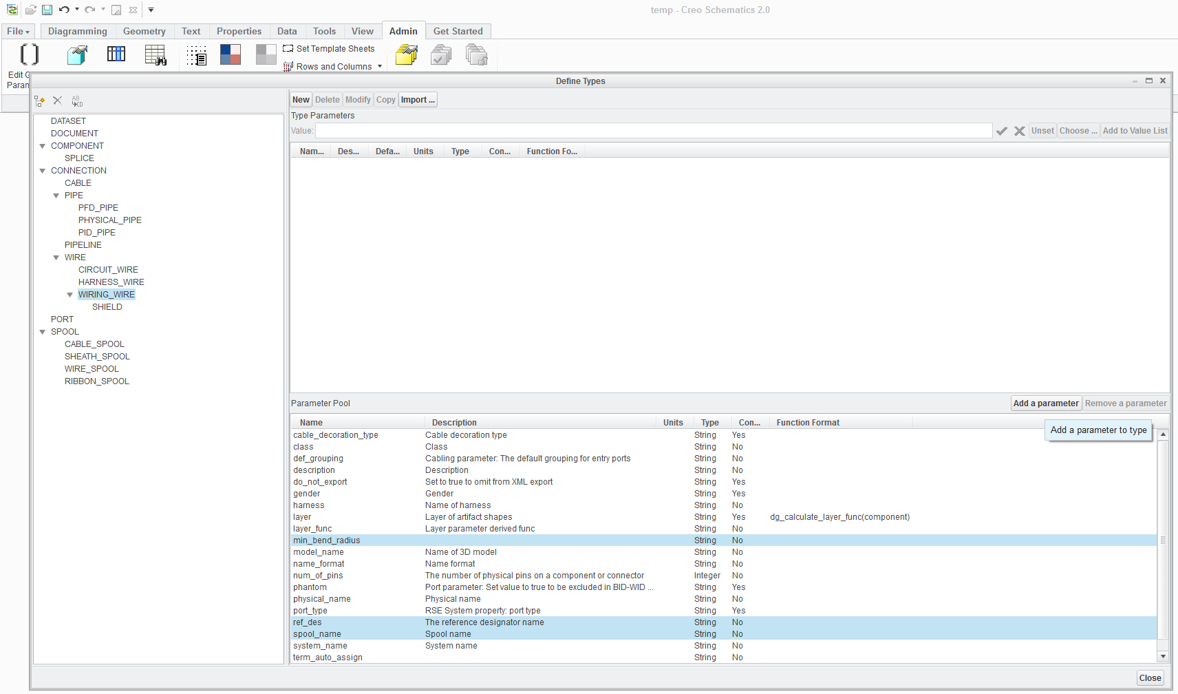
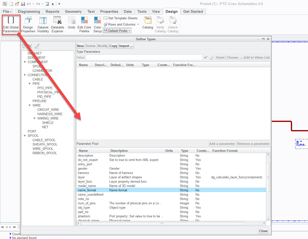
I'm assuming you are trying to use Add a parameter button to create a parameter. This button adds a parameter to an Object Type. To create a new parameter use the New or Import buttons at the top of the dialog. Import allows you import parameters from a parameter .csv file. To use the Add a parameter button you select the Object Type in left window pane, select a parameters or multiple parameters in the Parameter Pool pane (Add a Parameter only becomes active when both the Object Type and Parameter has been selected, and select Add a parameter button. To verify the parameters were added to the Object Type definition select a different Object Type and then re-select the Object Type you added the parameters to.
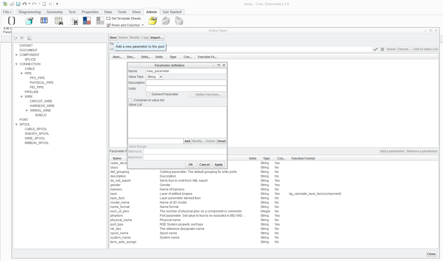
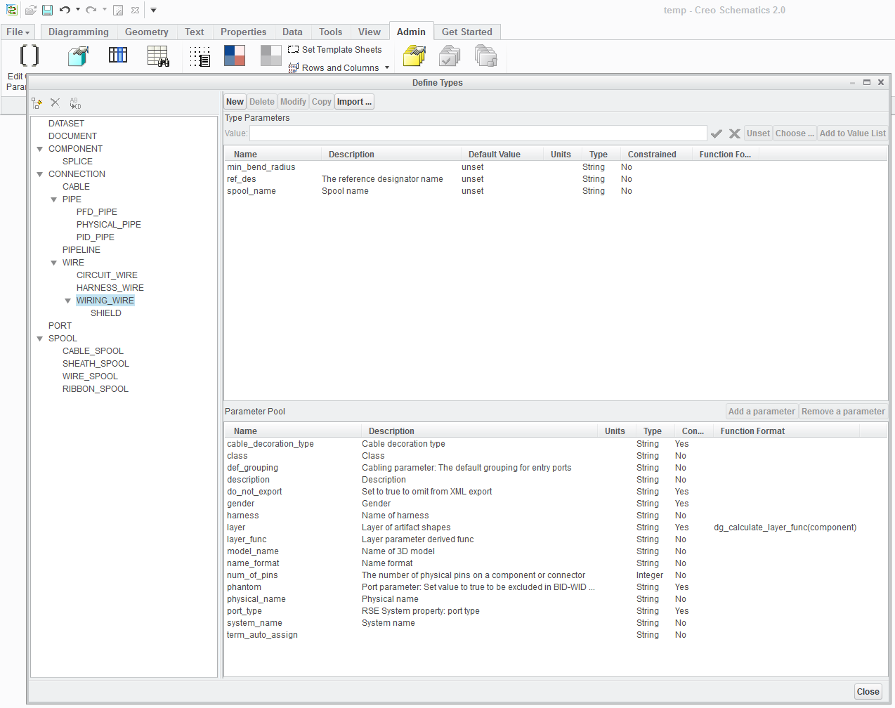
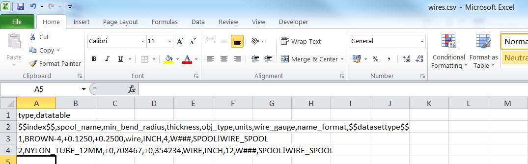
Your .csv file for the wire looks fine, you have the minimum number of parameters needed for the definition.
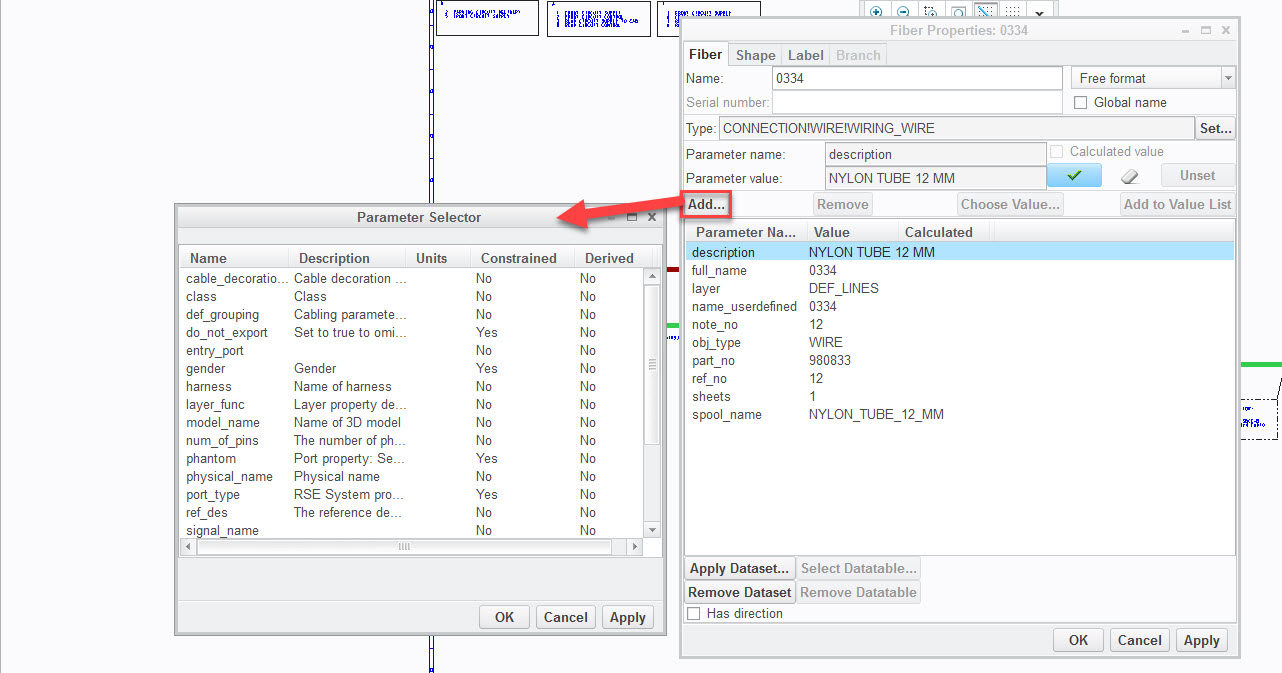
Add on the Fiber Properties dialog will only add parameters that have already been created in the Global Parameters dialog it doesn't create them if they are missing.
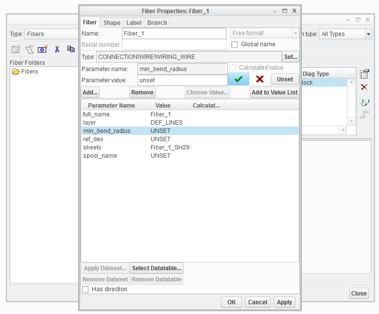
If you add the parameters to an Object Type you can set the Object Type in the Fiber Properties and the parameters associated with the Object Type are added.
5 REPLIES 5
Mar 17, 2017
11:34 AM
- Mark as New
- Bookmark
- Subscribe
- Mute
- Subscribe to RSS Feed
- Permalink
- Notify Moderator
Please log in to access translation
Mar 17, 2017
11:34 AM
Take a look at the Global parameters. The parameters need to be added here before you can import a datatable. Also check the .csv file that contains the datatable info. You also need to look at the shape properties. You should be able to add the parameter if it's created or you could also add the parameters by specifying them as part of an Object Type definition and setting the shapes Type property. If you need to see images I can add those.
Mar 20, 2017
04:37 AM
- Mark as New
- Bookmark
- Subscribe
- Mute
- Subscribe to RSS Feed
- Permalink
- Notify Moderator
Please log in to access translation
Mar 20, 2017
04:37 AM
Hello Kevin,
Thank you for your answer
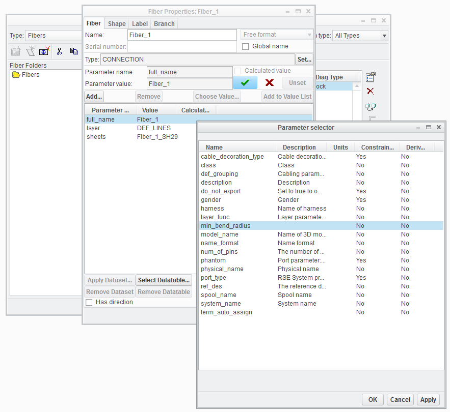
I already took a look at the global parameters but i can't add the ones I want (even someting simple as min_bend_radius), plese see picture below :
I think my csv file should be good, but i put a picture in case :
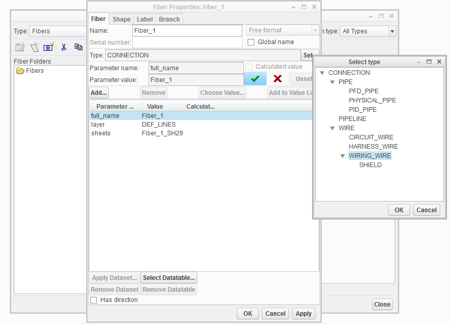
Also, if i directly edit the parameters by going in the fiber properties, I still can't add the ones i want :
I sent most pictures I could so that you may see an error hidden somewhere, who knows
I noticed that with the get started tab and using the sample catalog we directly have access to those parameters, so i guess it is something i have to configure but that isn't explained in the tutorial?
Best regards
Ambroise.
Mar 20, 2017
09:51 AM
- Mark as New
- Bookmark
- Subscribe
- Mute
- Subscribe to RSS Feed
- Permalink
- Notify Moderator
Please log in to access translation
Mar 20, 2017
09:51 AM
I'm assuming you are trying to use Add a parameter button to create a parameter. This button adds a parameter to an Object Type. To create a new parameter use the New or Import buttons at the top of the dialog. Import allows you import parameters from a parameter .csv file. To use the Add a parameter button you select the Object Type in left window pane, select a parameters or multiple parameters in the Parameter Pool pane (Add a Parameter only becomes active when both the Object Type and Parameter has been selected, and select Add a parameter button. To verify the parameters were added to the Object Type definition select a different Object Type and then re-select the Object Type you added the parameters to.
Your .csv file for the wire looks fine, you have the minimum number of parameters needed for the definition.
Add on the Fiber Properties dialog will only add parameters that have already been created in the Global Parameters dialog it doesn't create them if they are missing.
If you add the parameters to an Object Type you can set the Object Type in the Fiber Properties and the parameters associated with the Object Type are added.
Mar 20, 2017
11:39 AM
- Mark as New
- Bookmark
- Subscribe
- Mute
- Subscribe to RSS Feed
- Permalink
- Notify Moderator
Please log in to access translation
Mar 20, 2017
11:39 AM
Thank you so much for your help, I appreciate it!
So when I will try to route my wires in CreoParametric, it will recognize that min_bend_radius is a parameter he knows and will take it into account. And to go further any parameter that Parametric knows can be created and added in Schematics => correct?
One last question : How do we export the parameters created in schematics as csv? Is there a specific button or do we manually create a csv if we want to import in other designs the min_bend_radius? (for one parameter i agree it is not a big deal to do it manually, but i have more than min_bend_radius)
Thank you again Kevin!
Mar 21, 2017
11:11 AM
- Mark as New
- Bookmark
- Subscribe
- Mute
- Subscribe to RSS Feed
- Permalink
- Notify Moderator
Please log in to access translation
Mar 21, 2017
11:11 AM
When you export the design from Schematics the shape properties get exported to the .xml for import into Creo Cabling. If the Fiber properties are setup correctly, when you are in Creo Cabling you import the .xml file, select Spools>Create, you should see a new menu item From Logical, selecting this you will get a list of wire spools that were exported with the Schematics design, and select the spool(s) to create. From the Spools menu select Edit, select the spool(s) you want to Edit, you should see a list of spools, and the parameters should have the values you specified in Schematics. You can create the min_bend_radius, density, color, thickness, etc. parameters that are defined in Creo Cabling in Schematics with some exceptions being the Name and Type. These are already defined as system parameters. For a component such as a connector model_name from Schematics maps to Name in Cabling. For a Wire spool_name maps to Name. Some of the documentation and training materials make it sound as if the obj_type parameter that you create maps to Type, but it doesn't appear to; it appears the $$datasettype$$ maps to Type. You will also notice this with the Entry Port Type parameter; it appears the Type selection from the shape properties dialog (similar to the one shown for the Fiber properties in my previous post) maps to Type. In order for the values to transfer they have to be set correctly in Schematics otherwise it sets to the default value in Cabling. It's been a while since I've set this up so I'd have to try it out again to remember the settings that worked. Additional parameters not defined in Cabling get added as information parameters.
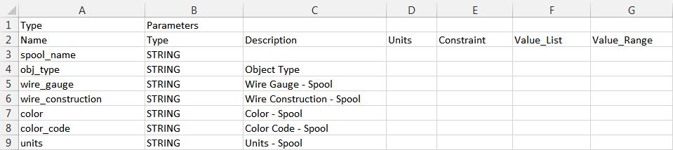
The .csv has a specific format that is shown in the help. Here is a partial .csv file showing the format; as a minimum you need to specify Name and Type. The first to rows are required.
The .csv needs to be created manually. Another option is you could specify values for the parameters for a wire in Cabling and Export the Logical Data. This will export the parameters in Cabling to an .xml file that can be imported into Schematics. Schematics will ignore the data it can't handle but will import the parameters. If the designs haven't been created yet you can create a design template. When you create a new design select the Use Template to specify the design template.
To create a design template and Pack Design. This creates a .rsd file that can be used as a template for new designs. Another option you for importing parameters and other items is to Export Design Properties. When you import to a design the design properties of the file are compared to those of the design. Items that are new or modified are indicated and created.


Top Tags
