
Turn on suggestions
Auto-suggest helps you quickly narrow down your search results by suggesting possible matches as you type.
Showing results for
Please log in to access translation
Turn on suggestions
Auto-suggest helps you quickly narrow down your search results by suggesting possible matches as you type.
Showing results for
- Community
- Creo+ and Creo Parametric
- System Administration, Installation, and Licensing topics
- Re: SAVING PLANES WITHIN A STEP FILE
Translate the entire conversation x
Please log in to access translation
Options
- Subscribe to RSS Feed
- Mark Topic as New
- Mark Topic as Read
- Float this Topic for Current User
- Bookmark
- Subscribe
- Mute
- Printer Friendly Page
SAVING PLANES WITHIN A STEP FILE
Jun 23, 2014
01:32 PM
- Mark as New
- Bookmark
- Subscribe
- Mute
- Subscribe to RSS Feed
- Permalink
- Notify Moderator
Please log in to access translation
Jun 23, 2014
01:32 PM
SAVING PLANES WITHIN A STEP FILE
When I save an assembly as a step file, the assembly planes and additional planes that I have in the assembly do not store in the step file.
How do I enable the planes to be stored as well?
Kevin
This thread is inactive and closed by the PTC Community Management Team. If you would like to provide a reply and re-open this thread, please notify the moderator and reference the thread. You may also use "Start a topic" button to ask a new question. Please be sure to include what version of the PTC product you are using so another community member knowledgeable about your version may be able to assist.
Labels:
- Labels:
-
General
10 REPLIES 10
Jun 23, 2014
02:26 PM
- Mark as New
- Bookmark
- Subscribe
- Mute
- Subscribe to RSS Feed
- Permalink
- Notify Moderator
Please log in to access translation
Jun 23, 2014
02:26 PM
I do not think planes are part of the STEP specification and are therefore not a recognized element.
If orientation is critical for the recipient of your file, you might conside placing curves such as a rectangle or circle on specific planes so that the recipient can generate their own planes or coordinate systems based on these curve features. Curves are optional in exporting to STEP.
Jun 23, 2014
09:19 PM
- Mark as New
- Bookmark
- Subscribe
- Mute
- Subscribe to RSS Feed
- Permalink
- Notify Moderator
Please log in to access translation
Jun 23, 2014
09:19 PM
I looked and there's a ton of STEP formats. STEP was to avoid the cacophany of IGES, where everyone 'supported' IGES but used limited and unique subsets, by specifying test suites. Don't support the suite, can't claim compatibility.
Apparently the STEP group gave that up in favor of suppliers just vouching for it. It was a result of trying to make STEP all things to all people for the sales value, but it overextended the ability of the standards orgs to create the tests.
Now it falls under ISO 10303. From Wikipedia, just the mechanical top of the iceberg:
Mechanical:
- AP 201, Explicit draughting. Simple 2D drawing geometry related to a product. No association, no assembly hierarchy.
- AP 202, Associative draughting. 2D/3D drawing with association, but no product structure.
- AP 203, Configuration controlled 3D designs of mechanical parts and assemblies.
- AP 204, Mechanical design using boundary representation
- AP 207, Sheet metal die planning and design
- AP 209, Composite and metallic structural analysis and related design
- AP 214, Core data for automotive mechanical design processes
- AP 235, Materials information for the design and verification of products
- AP 236, Furniture product data and project data
- AP 242, Managed model based 3d engineering (under development)
From ISO on ISO-10303-203, 400 HTML pages, 198 swiss francs, ~$220 US :
The following are within the scope of ISO 10303-203:2011:
- products that are mechanical parts and assemblies;
- product definition data and configuration control data pertaining to the design phase of a product's development;
- representation of an instance of a part in an assembly through its usage in a sub-assembly;
- three-dimensional shape representations of a part that includes:
- geometrically and topologically bounded wireframe models;
- geometrically bounded surface models;
- topologically bounded solid models with facetted, elementary and advanced faces;
- non surface bounded solid models including constructive solid geometry, curve swept and other swept solids, thickened face solid;
- solids with construction history;
- topologically bounded manifold surface and subsurface and non manifold surface models;
- topologically bounded compound models;
- geometric validation properties to allow the translation of geometric shape representations (advanced boundary representation and faceted boundary representation solids) to be checked for quality;
- geometric and dimensional tolerances applied to geometric shape representations;
- materials and their composition of chemical substance;
- composite material structure and shape;
- catalogue data characterized by property value pairs;
- three-dimensional presentation of product data:
- arranging geometric elements in layers and groups and assigning colours;
- presentation styles for points, curves, surfaces and sections, including hatching and tiling;
- saved views of particular camera positions and sections;
- textual annotation and notes applied to geometric elements;
- presentation of geometric and dimensional tolerances;
- technical drawings as two-dimensional presentation of product data.
This won't be enough. See the other related specs, some needed to tell how to read this one:
http://www.iso.org/iso/home/store/catalogue_ics/catalogue_ics_browse.htm?ICS1=25&ICS2=040&ICS3=40&
Jun 23, 2014
02:38 PM
- Mark as New
- Bookmark
- Subscribe
- Mute
- Subscribe to RSS Feed
- Permalink
- Notify Moderator
Please log in to access translation
Jun 23, 2014
02:38 PM
I believe I found my own answer. Within the config.pro there is a "step_export_format", the value for this has pull down options to choose from and the value should be "ap203_e2".
Then all planes and axes will translate to the STEP file
Jun 23, 2014
03:01 PM
- Mark as New
- Bookmark
- Subscribe
- Mute
- Subscribe to RSS Feed
- Permalink
- Notify Moderator
Please log in to access translation
Jun 23, 2014
03:01 PM
I am not sure where you read that. Using this setting did not include planes in my quick test (Creo 2.0 M040)
http://www.proesite.com/cgi-bin/find_option.cgi?srch=STEP_EXPORT_FORMAT&ver=creo1
However, there is something funny going on. When I choose ap203_e2 for config.pro it switches back to 203_IS_EXT after creating the STEP file. The option for ap203_e2 is also not available in the STEP configuration editor during exporting.
I wonder if this was a bug in the export that was fixed in a later version.
Can you confirm that your version is behaving properly and that indeed you are getting planes through your STEP file? I cannot get it to work.
Jun 23, 2014
08:40 PM
- Mark as New
- Bookmark
- Subscribe
- Mute
- Subscribe to RSS Feed
- Permalink
- Notify Moderator
Please log in to access translation
Jun 23, 2014
08:40 PM
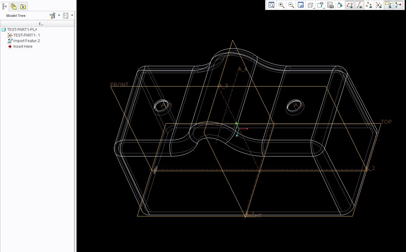
I use ap214_is and it askes if you want to export Annotations. Which imported back in looks like this.
Jun 23, 2014
09:24 PM
- Mark as New
- Bookmark
- Subscribe
- Mute
- Subscribe to RSS Feed
- Permalink
- Notify Moderator
Please log in to access translation
Jun 23, 2014
09:24 PM
Matt; confirmed. I needed to delete the step_config.pro file in the working folder to get this to work.
Never considered planes to be annotation 
Jun 24, 2014
10:22 AM
- Mark as New
- Bookmark
- Subscribe
- Mute
- Subscribe to RSS Feed
- Permalink
- Notify Moderator
Please log in to access translation
Jun 24, 2014
10:22 AM
Hmmm, I just tried the ap214_is setting and all it did was give me a note (STEP_COMMENTS) in the model tree. No planes, etc. Bummer! But only for those getting my exported STEP file. I use a template on the way in so I get all my rules-based layers, planes, etc.
For reference I'm on creo elements/pro 5.0.
Jun 24, 2014
10:11 AM
- Mark as New
- Bookmark
- Subscribe
- Mute
- Subscribe to RSS Feed
- Permalink
- Notify Moderator
Please log in to access translation
Jun 24, 2014
10:11 AM
Interesting topic gents, here's some more info:
It's funny how there is so little info on what these settings do, no real explanation.
Jun 24, 2014
11:32 AM
- Mark as New
- Bookmark
- Subscribe
- Mute
- Subscribe to RSS Feed
- Permalink
- Notify Moderator
Please log in to access translation
Jun 24, 2014
11:32 AM
Here's a good background, www.mel.nist.gov/div826/library/doc/jcise1.pdf
A STEP file analyzer from the National Institute of Standards and Technology, NIST; should be useful for sorting out transfer problems incoming and outgoing: http://www.nist.gov/el/msid/infotest/step-file-analyzer.cfm
Jun 24, 2014
12:04 PM
- Mark as New
- Bookmark
- Subscribe
- Mute
- Subscribe to RSS Feed
- Permalink
- Notify Moderator
Please log in to access translation
Jun 24, 2014
12:04 PM
Excellent find, David!


Top Tags
