
Turn on suggestions
Auto-suggest helps you quickly narrow down your search results by suggesting possible matches as you type.
Showing results for
Please log in to access translation
Turn on suggestions
Auto-suggest helps you quickly narrow down your search results by suggesting possible matches as you type.
Showing results for
Community Tip - You can Bookmark boards, posts or articles that you'd like to access again easily! X
- Community
- Creo+ and Creo Parametric
- System Administration, Installation, and Licensing topics
- stl modelling, a tale of three software pacakges
Translate the entire conversation x
Please log in to access translation
Options
- Subscribe to RSS Feed
- Mark Topic as New
- Mark Topic as Read
- Float this Topic for Current User
- Bookmark
- Subscribe
- Mute
- Printer Friendly Page
stl modelling, a tale of three software pacakges
Nov 28, 2012
04:12 PM
- Mark as New
- Bookmark
- Subscribe
- Mute
- Subscribe to RSS Feed
- Permalink
- Notify Moderator
Please log in to access translation
Nov 28, 2012
04:12 PM
stl modelling, a tale of three software pacakges
H i All
I have a problem which we need a workable solution for.
We need to make this as simple as possible as we are looking at processing this on evey batch of wheels so we can alter the programming to best suit the wheel, as heavy wheels damage our machinery.
We are trying to intergrate three software application to work as one process
these are
Creo 1.0
Vericut Machining simulation
Tecnogamma lazer scanner
What we are doing, the lazer scanner measures the hot forged wheel at the end of the roll process and it create a 3D STL file of the wheels surface from the collected data. as below
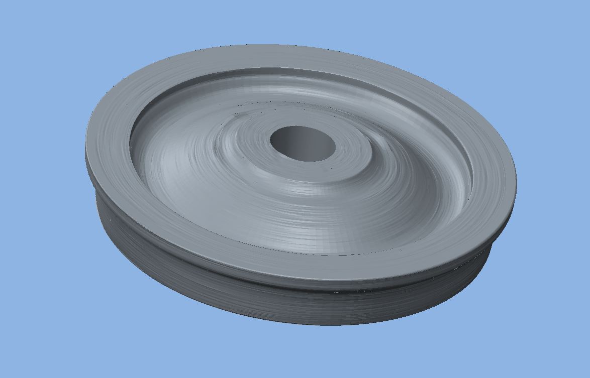
Now we are trying to load this into Vericut, so we can get an idea of just how much metal is really being removed, but it doesn't like the fact that it is not concentric.
So, I have been trying to create a cross section by loading the STL file into a part and then creating a cross section, with the idea that I can use a sketch to create a revole feature for both the heavy side and the light side of the wheel to estimate the runout, I can then run the simulation on both and calculate the mass removed on each cut for both models.
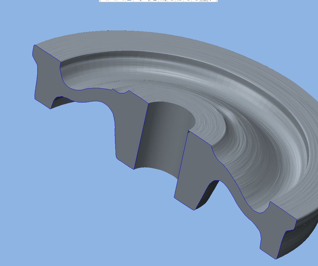
Now the problem is, I can get this far, but it won't reference the STL part to allow me to create a sketch. I would just like to sketch on half of the cross section to create a revole feature.
Is there a solution to this
Thank you
Peter
This thread is inactive and closed by the PTC Community Management Team. If you would like to provide a reply and re-open this thread, please notify the moderator and reference the thread. You may also use "Start a topic" button to ask a new question. Please be sure to include what version of the PTC product you are using so another community member knowledgeable about your version may be able to assist.
Labels:
- Labels:
-
General
3 REPLIES 3
Nov 28, 2012
04:16 PM
- Mark as New
- Bookmark
- Subscribe
- Mute
- Subscribe to RSS Feed
- Permalink
- Notify Moderator
Please log in to access translation
Nov 28, 2012
04:16 PM
Will analysis not provide you with a centroid location? This should give you some idea of the runout, direction and degree.
Nov 29, 2012
04:17 PM
- Mark as New
- Bookmark
- Subscribe
- Mute
- Subscribe to RSS Feed
- Permalink
- Notify Moderator
Please log in to access translation
Nov 29, 2012
04:17 PM
We really need to be able to create a part from the section of the STL file, so we cun run it through Vericut, this will give us a real estimate on just how much contact the tip has at any point of the process, see this youtube link
The tool comes into shot around 40 second, we can see the contact are
Peter
Nov 29, 2012
04:41 PM
- Mark as New
- Bookmark
- Subscribe
- Mute
- Subscribe to RSS Feed
- Permalink
- Notify Moderator
Please log in to access translation
Nov 29, 2012
04:41 PM
Now I understand. I don't know that CAD/CAM will solve this without some special coding. I would suggest developing a maximum material "envelope" and programming to that.
Take a look at how the actual part is constrained in the lathe/mill (axle bore or other feature) and do an analysis on several castings to determine the variation based on the best effort located on the tool holding feature. That way, you can program the tool-path for the expected worst case where in some cases, the tool may not make a cut on the 1st pass, but you didn't break any tools either.
in CAD, you do have interference tools using cross sections. You can make an overlay model of several castings to determine the various profiles. It is a bit of up-front effort but once you have honed the process, you won't need to scan every wheel.
Of course, the machinist can also gauge each casting to get an idea of where to start if runtime is an issue. I would think the variation is not significant so a fairly tight envelope can be developed over a relatively short run of parts. after that, some sample scans can make sure the tooling remains within your defined parameter.
Sometimes, CAD/CAM isn't the final answer. Often times it just required common sense.


Top Tags
