
Turn on suggestions
Auto-suggest helps you quickly narrow down your search results by suggesting possible matches as you type.
Showing results for
Please log in to access translation
Turn on suggestions
Auto-suggest helps you quickly narrow down your search results by suggesting possible matches as you type.
Showing results for
Community Tip - Want the oppurtunity to discuss enhancements to PTC products? Join a working group! X
- Community
- Creo+ and Creo Parametric
- 3D Part & Assembly Design
- Re: Drawings unstable in Creo 2.0?
Translate the entire conversation x
Please log in to access translation
Options
- Subscribe to RSS Feed
- Mark Topic as New
- Mark Topic as Read
- Float this Topic for Current User
- Bookmark
- Subscribe
- Mute
- Printer Friendly Page
Drawings unstable in Creo 2.0?
Jun 22, 2012
02:28 AM
- Mark as New
- Bookmark
- Subscribe
- Mute
- Subscribe to RSS Feed
- Permalink
- Notify Moderator
Please log in to access translation
Jun 22, 2012
02:28 AM
Drawings unstable in Creo 2.0?
I just completed a very comprehensive machining drawing and I must say that between 2000i and Creo 2.0, the drawing had become seriously unstable.
1st I was dealing with some very annoying graphics artifacts. Ones where simply moving an annotation feature would blank out the feature. More often than not, I would have to regenerate the drawing to get things to unhighlight or come back to a visible state. Seriously annoying indeed!
Then I had whole blocks of dimensions and other features just -move-. They jumbled themselves up left and right generally undoing a lot of careful placement that I was -doing-. It happened sometime between switching to the model and drawing, and poof, I again had to fix a couple of dozen annotation features.
Am I the only one? ...or is this something that has become the norm? Seriously, in 2000i, it was set it and forget it. Now I don't know how people keep from pulling their hair out.
I am on an approved platform with the approved drivers... etc.
This thread is inactive and closed by the PTC Community Management Team. If you would like to provide a reply and re-open this thread, please notify the moderator and reference the thread. You may also use "Start a topic" button to ask a new question. Please be sure to include what version of the PTC product you are using so another community member knowledgeable about your version may be able to assist.
Labels:
- Labels:
-
General
141 REPLIES 141
Jul 24, 2012
05:52 PM
- Mark as New
- Bookmark
- Subscribe
- Mute
- Subscribe to RSS Feed
- Permalink
- Notify Moderator
Please log in to access translation
Jul 24, 2012
05:52 PM
Antonius Maximus (sorry, it just sounds Roman and cool!): I can turn mine off with layers that use rules. Some of the rules don't work 100%, but, most do. I think there are some glitches, but 99% works great.
Read up on "extending rules" (you can use a quick new assy to extend rules to lower parts but delete the part layers first) and try these start parts:
Jul 24, 2012
07:09 PM
- Mark as New
- Bookmark
- Subscribe
- Mute
- Subscribe to RSS Feed
- Permalink
- Notify Moderator
Please log in to access translation
Jul 24, 2012
07:09 PM
Holy cow! 42 pages of rules? I never used any rules! I create a layer called "HIDEME" and add stuff. Has always worked in the past.
Jul 24, 2012
06:29 PM
- Mark as New
- Bookmark
- Subscribe
- Mute
- Subscribe to RSS Feed
- Permalink
- Notify Moderator
Please log in to access translation
Jul 24, 2012
06:29 PM
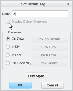
So I totally see how this plane and annotation set are a bit goofy. I think the entire problem is that, for tags placed On Datum, you cannot turn off "Display Datum Graphics". See pointer in image below.
There's a clue if you go to the Annotations tab and pull down the Detail Tree. Expanding your annotation "A", you'll see 'Datum Graphics" and the datum plane hiding under there. You cannot unlink the two (easily). If you right-click on the annotation, you can select Erase and actually hide the datum.
I was able to perform some type of weird maneuver to Unerase annotation which brought back the "A" but left the datum erased! This, I believe, is what you've been trying to do the entire time.
One the drawing, I was able to have all 3 annotations show up with no planes at all... or selectively turn the planes on as I needed them. It's definitely not working right because the results are inconsistent. But I was able to make an acceptable drawing using a combination of the Detail Tree, toggling the annotation, and erasing/unerasing the annotation.
To me, I think the entire thing would be fixed if they'd enable the ability to turn off the Display Datum Graphics switch.
Thanks!
-Brian
Jul 24, 2012
07:03 PM
- Mark as New
- Bookmark
- Subscribe
- Mute
- Subscribe to RSS Feed
- Permalink
- Notify Moderator
Please log in to access translation
Jul 24, 2012
07:03 PM
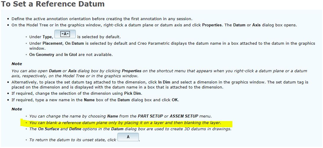
Brian, it is still an issue. The manual plainly says in several places that you should be able to put the plane used for datum tag annotation on a hidden layer and have it actually hide. But it doesn't.
And yes, it is very goofy as sometime the datum plane hides and can't be recovered for viewing.
Can you get to CS cases? Mine is 1088820
I don't want to take this part of the discussion too far off course here. I was told that it behaved as expected and according to the manual it doesn't, and that is why I pushed it further. At first I was told to use display states, which works, but it is not acceptable behavior. The "label" and the "plane" should should not have visibility constraints tied to each other. One is annotation, and the other is a datum feature. I should be able to choose which I want to see easily.
Jul 24, 2012
07:26 PM
- Mark as New
- Bookmark
- Subscribe
- Mute
- Subscribe to RSS Feed
- Permalink
- Notify Moderator
Please log in to access translation
Jul 24, 2012
07:26 PM
Yeah, I agree Antonius... it's not working as it's supposed to. I think someone either inadvertently left out the ability to turn OFF the datum using the switch I noted in the last message... or they just plain missed it and didn't realize it wasn't working right.
I cannot view your CS number... it's locked for PTC's eyes only. They do that sometimes. I have my theories on why... but no matter. I'm sure they'll put out a bug fix in a future production release. We struggled through waiting for a bug fix on Wildfire 5... and it took a good bit of time.
Jul 24, 2012
11:03 PM
- Mark as New
- Bookmark
- Subscribe
- Mute
- Subscribe to RSS Feed
- Permalink
- Notify Moderator
Please log in to access translation
Jul 24, 2012
11:03 PM
Just started to play with it and I would say in PTCs way of thinking it's working as it should although strange things show up. My thought is it goes back to the image Antonius posted and what the datum symbol attaches to which, as has been discussed in other topics, doesn't look like it was updated for Creo 1 since those are directions for WF5 and earlier but I don't know how far back it goes. What I'm noticing is an additional layer of functionality and they also changed the way you work with annotations. Seems they are moving away from having to put annotations on layers since they added the Detail Tree and they have changed how you handle annotations since the operation is now erase/show instead of hide/unhide. So even though you can put annotations on a layer it does no good to hide it in the model because the operation for the annotation elements is now erase/show, haven't tried to see how it behaves in drawings. So for the first option on the datum definition dialog my guess would be because the datum symbol is attached to the datum feature the datum graphics are needed in order to display the datum symbol annotation. For Dim and Geometry options the datum graphics aren't needed because it's not attached to a datum feature. Haven't tried the Gtol option yet to see what that gives. I started lookng at the Combined states. I found them to work descent in the model although it probably depends on how familiar and comfortable you are with creating annotations and combined states. Started looking at drawings but haven't messed with it enough yet to know what it gives but think I understand some of it.
Jul 24, 2012
11:53 PM
- Mark as New
- Bookmark
- Subscribe
- Mute
- Subscribe to RSS Feed
- Permalink
- Notify Moderator
Please log in to access translation
Jul 24, 2012
11:53 PM
It's just sort of a mess Kevin. I tried the drawing tools and the whole thing is just messy and unclear. As you pointed out, the documentation is not updated and the operation and use of the various hide/unhide, erase/unerase options get murky.
I understand your point about needing to show the datum using the "On Datum" option. I initially agreed with the logic. But then after thinking about it... there are reasons why you'd need the datum tag without the actual datum plane.In fact, in all previous versions of Pro/E, you could easily do this. The cleanest way to present the "set datum" on the drawing is without the datum... so upon re-thinking it, I do not agree with the logic that forces the datum display to be on.
It just seems that someone dropped the ball on this one. I can imagine PTC will fix this in an upcoming production release of Creo 2.
If not... and if PTC stands on it's original decision that this is "intended functionality", Antonius needs to keep escalating the call until someone who understands the underlying problem finally gets eyes on his call.
Thanks!
-Brian
Jul 25, 2012
01:25 AM
- Mark as New
- Bookmark
- Subscribe
- Mute
- Subscribe to RSS Feed
- Permalink
- Notify Moderator
Please log in to access translation
Jul 25, 2012
01:25 AM
So I am curious... You ASME Y14.41 peeps.
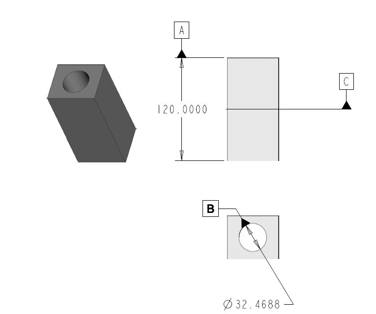
I work a lot with cylindrical objects with a lot of features machined in the ends and a lot of concentric cylindrical faces. I need to orient "clocking" and therefore I typically have a cylindrical datum...say [-A-] and a perpendicular (normal) plane through [-A-] as [-B-]. Then you have [-C-] to orient clocking normal to [-B-] along the axis of [-A-].
How do you properly represent [-C-] in an ASME Y14.41 display? I'm thinking ISO or skewed of course, I can see how you would do it in Orthographic mode. But even then, you would only want to see a single line, not the double plane lines of the plane graphics.
Jul 25, 2012
06:20 PM
- Mark as New
- Bookmark
- Subscribe
- Mute
- Subscribe to RSS Feed
- Permalink
- Notify Moderator
Please log in to access translation
Jul 25, 2012
06:20 PM
A further thought... This is pretty indicative of my parts except this is simple... But there is a missing datum for completeness... datum [C]. Again, how would you show this per the standard?
Jul 25, 2012
10:55 PM
- Mark as New
- Bookmark
- Subscribe
- Mute
- Subscribe to RSS Feed
- Permalink
- Notify Moderator
Please log in to access translation
Jul 25, 2012
10:55 PM
Based on the reading it depends on what you are after but two options would be use all four holes or use one. If you use all four you would just add the datum symbol to the frame shown. If you use one you need to add two dimensions with FCF and attach the datum symbol to the individual feature dimension FCF. Same thing applies to the other two holes if those are the ones you want to use.
Jul 25, 2012
03:07 AM
- Mark as New
- Bookmark
- Subscribe
- Mute
- Subscribe to RSS Feed
- Permalink
- Notify Moderator
Please log in to access translation
Jul 25, 2012
03:07 AM
I'm not agreeing with the logic either I'm just pointing out what I think is causing the issue based on what I'm seeing. The other thing is I'm using Creo 1 so I may or may not being seeing the same thing. As far as I can tell we're all seeing the same thing in the model environment. The drawing environment is different as I haven't used it for anything other than trying out simple things but set datums don't display on my setup only regular datum planes do. For my setup having the ability to toggle on and off the datum graphics for datum features wouldn't have any effect since the set datums don't show on drawings. The tags show and are movable like before.
What I see them doing is something similar to what they did with the Show/Erase Dialog. I do think we have different opinions on what the problem is. I don't think it's the datum graphics setting that's the problem I think it's how they programmed the new work flow and how annotations are handled. Yes you could easily display the datum tag without the datum in WF5 and earlier but you also didn't have the Detail Tree and you could also hide/unhide annotation elements by selecting them or putting them on layers. The handling for both the set datum feature and the annotation associated with it was the same so it was easily hidden by putting it on a layer. Now it seems you have a feature that can be hidden that has an annotation element that has to be eraesd. Maybe the way it's programmed there is a conflict. Then again I'm not a programmer so maybe it could be as easy as allowing access to the datum graphics option.
Jul 25, 2012
03:19 AM
- Mark as New
- Bookmark
- Subscribe
- Mute
- Subscribe to RSS Feed
- Permalink
- Notify Moderator
Please log in to access translation
Jul 25, 2012
03:19 AM
I agree Kevin... it could certainly just be the new implementation of items in the Detail Tree. No matter what the problem, it's easily reproduced so hopefully a developer from PTC can just look at it and immediately know what's happening. I'm sure it's mostly a nuisance right now.
While I like the idea of the Detail Tree... the jury's still out on the way the annotations are being handled. I've just never really understood all the machinations we have to go through with annotations. There's so many switches. There's the Annotation On/Off toggle... plus the 3D Notes/Notes as Names switches... then layers... and now another level to mess with in the Detail Tree.
It just feels like the annotations are all over the place when they should just be like "notes with special features". Instead they're a big nest of options and switches and buttons that make me a bit dizzy.
Or maybe it's just that it's 3:30am and I'm still posting on this site! I may need sleep at some point.
Jul 25, 2012
03:36 AM
- Mark as New
- Bookmark
- Subscribe
- Mute
- Subscribe to RSS Feed
- Permalink
- Notify Moderator
Please log in to access translation
Jul 25, 2012
03:36 AM
Sleep is highly over rated! 
Jul 25, 2012
03:34 AM
- Mark as New
- Bookmark
- Subscribe
- Mute
- Subscribe to RSS Feed
- Permalink
- Notify Moderator
Please log in to access translation
Jul 25, 2012
03:34 AM
To be clear, Kevin, I am not having a problem in the drawing (show/erase/delete)... I am having a problem in the part file (hide/unhide).
Well, actually.. in the drawing, moving the datum tag causes Creo 2.0 to crash... but that's another story... and CS call. I've been able to re-create that one too.
Jul 25, 2012
04:01 AM
- Mark as New
- Bookmark
- Subscribe
- Mute
- Subscribe to RSS Feed
- Permalink
- Notify Moderator
Please log in to access translation
Jul 25, 2012
04:01 AM
I do think I've found some more info that might be help if you haven't already seen it. It requires a picture which willhave to wait till tomorrow.
Jul 25, 2012
05:09 PM
- Mark as New
- Bookmark
- Subscribe
- Mute
- Subscribe to RSS Feed
- Permalink
- Notify Moderator
Please log in to access translation
Jul 25, 2012
05:09 PM
I was playing with it again today.
With the advice submitted so far, and seriously appreciated, BTW! ... I found the simples way to avoid unwanted graphics appearance of datum planes assigned to datum tags is to "remove from state" with a simple right click of the mouse on the annotation in the Detail Tree and select Remove From State. This will remove the annotation, plane, and reference form the Detail Tree in the model.
To re-echo the annotation, and subsequent plane, you go to the model tree and right click on the annotation and pick Show Annotations and select it in the dialog box.
There are a few caveats here:
1. If you re-associated the datum tag to a new feature like a dim or gtol, you may not see it again in the model as you originally placed it.
2. Kevin's wise words of using a plane solely for making the datum tag is appropriate, as you will not see it again when you "remove from state" (Default All).
3. Even though you removed the datum from the model state, you can still echo the datum annotation in the drawing. At least you can when you do not use stated to define view on the drawing which I don't do typically.
This datum thing is seriously convoluted. Even though the system generates planes and axes for datum tags, they are treated differently than construction datum planes and axis when you annotate a datum tag to them.
I am also missing the ability to move datum tags applied to cylinders. For doing "paperless" ASME Y14.41 displays, you would think you would want to move the datum tag around for best presentation. The only option is to flip the triangle or go back to the properties and select a new location on the surface. You cannot move the leader though.
Jul 25, 2012
01:17 AM
- Mark as New
- Bookmark
- Subscribe
- Mute
- Subscribe to RSS Feed
- Permalink
- Notify Moderator
Please log in to access translation
Jul 25, 2012
01:17 AM
-If- it was consistent I could -almost- agree with you. But the fact that you can toggle off the annotation but not toggle off the plane doesn't make sense.
And as stated before, you will also find occasions where this tagged datum will just disappear. I think Brian is seeing what I mean. But yes, it has something to do as to whether it has been shown in a drawing or not.
All in all, I want to take a snapshot of a model and I don't want some datum messing up the pretty portrait. And I shouldn't have to go and definte display states to do that.
And you know I will keep pushing this. It was the lack of control of annotation that made Pro/E look pretty silly in a recent life... and it was a contributor to PTC loosing a handful of seats. In a way, this is an age-old problem.
Jul 25, 2012
05:16 PM
- Mark as New
- Bookmark
- Subscribe
- Mute
- Subscribe to RSS Feed
- Permalink
- Notify Moderator
Please log in to access translation
Jul 25, 2012
05:16 PM
A new problem cropped up today in detailling. I had already reported this to CS but didn't have all the facts. Today it became clear there is a bug in the presentation of datum tags on drawings. It has something to do with re-associating datum tags to gtol or dims. The text will become bold as it is in the models. It soon resolves itself but for the time being, it is problematic as this does plot with the wrong font settings. This is a screencap of the PDF, stroked font PDF plot output... [B] was moved from the cylindrical surface to the dimension.
...and wouldn't you know it. I tried to move the [B] datum and it crashed all my sessions!
I think this answers my original question...
YES, CREO 2.0 DETAILING IS QUITE UNSTABLE!
Aug 28, 2012
03:15 PM
- Mark as New
- Bookmark
- Subscribe
- Mute
- Subscribe to RSS Feed
- Permalink
- Notify Moderator
Please log in to access translation
Aug 28, 2012
03:15 PM
We just purchased several license of Sigmetrix GD&T Advisor. It places GD&T symbols using ASME or ISO rules as Annotations. Very cool add-in for Creo!!!
Aug 28, 2012
04:10 PM
- Mark as New
- Bookmark
- Subscribe
- Mute
- Subscribe to RSS Feed
- Permalink
- Notify Moderator
Please log in to access translation
Aug 28, 2012
04:10 PM
Yes Mitch...
I like the GD&T Advisor, too... it's a brand new product that was literally just released a few weeks ago. We demo'ed it where I work. It is a very cool add-in for Creo... but it's important to mention it's $3500 per seat.
For someone like Tom (Antonius), that's another $3500 to just to force Creo to create annotations correctly. And GD&T advisor doesn't give you the flexibility to show tolerances in all of the different ways specified in the ASME/ISO documents. It gives you compliant GD&T annotations... but if there are two or three variants which are also allowed, it does not necessarily handle all of them.
We specifically asked this technical point during our demonstration. Right now, you get a compliant annotation... but perhaps not the one you want. When you're trying to adhere strictly to an annotation scheme dictated by your customer, you can't just tell them "Hey sorry but my GD&T tool creates the annotations ONE WAY, I can't change them to the way you're used to seeing them."
Please don't misunderstand. I am not attacking GD&T Advisor... I like the product. I'm just saying it's not a magic bullet solution to the problem of GD&T in Creo. It helps... but the product is still very new and there's still some room for growth ... some features are still beyond it's capabilities.
Thanks!
-Brian
Aug 28, 2012
11:06 PM
- Mark as New
- Bookmark
- Subscribe
- Mute
- Subscribe to RSS Feed
- Permalink
- Notify Moderator
Please log in to access translation
Aug 28, 2012
11:06 PM
Thanks for the heads up, Mitch and thank you, Brian for your very astute observations.
I would only add one other question in that does the "advisor" allow you to see their annotation on Creo comparable viewers? And does it show the advisor annotation when the drawing is opened in Creo if they do not have the license. The latter question here is a biggy as PTC has at least seen to it that their extension modules are embedded for use on other seats.
This very much reminds me of what Draftpak did for Cadkey.
If I were heavily engaged in tolerance analysis and critical GTOL requirements (more than I normally am), it might be worth the investment. I would also be compensated accordingly so that would be appropriate.
Today, for the most part, the challenge is getting -my- needs met by the tools I have at hand. My needs are simple compared to the efforts of PTC in Y14.41 and the effort that went into Advisor. I definitely cannot afford even a minor hit to the budget to get what I consider basic drafting tools. But again, I am pleased to see someone interface such a nice little 3D party tool into Creo. Maybe others will be encouraged to build some user friendly UI for the basic Creo package.
Aug 29, 2012
12:34 AM
- Mark as New
- Bookmark
- Subscribe
- Mute
- Subscribe to RSS Feed
- Permalink
- Notify Moderator
Please log in to access translation
Aug 29, 2012
12:34 AM
Think of GD&T Advisor as a tool which helps you create native Creo GD&T annotations. It streamlines the process making it faster and much easier. It also has a GD&T encyclopedia if you need advice or guidance as you define your tolerancing. And, finally, it has enough intelligence to help you create the right tolerance callout for specific situations. It literally does "advise" you on the right thing to do... and backs up it's information with direct links to the standards. If you follow GD&T Advisor and suddenly the company "checker" redlines your work and claims you're applying the tolerance incorrectly, GD&T Advisor will actually point directly to the standard (chapter and verse) to back you up.
However, all it's really doing is creating native Creo GD&T. So... there is no need for a special viewer or an embedded module that travels with your files.
As for your wish that someone would build a user friendly UI for the base package... I've suggested it to the PTC Developers. I've mentioned it online. So far the reaction has been a solid "meh". One day I plan to give it a try myself... if I can ever get out from under the avalanche of work I've been buried under these past few weeks!
- « Previous
- Next »


