
Turn on suggestions
Auto-suggest helps you quickly narrow down your search results by suggesting possible matches as you type.
Showing results for
Please log in to access translation
Turn on suggestions
Auto-suggest helps you quickly narrow down your search results by suggesting possible matches as you type.
Showing results for
Community Tip - New to the community? Learn how to post a question and get help from PTC and industry experts! X
- Community
- Creo+ and Creo Parametric
- 3D Part & Assembly Design
- Re: Edges' color change between SHADING WITH EDGES...
Translate the entire conversation x
Please log in to access translation
Options
- Subscribe to RSS Feed
- Mark Topic as New
- Mark Topic as Read
- Float this Topic for Current User
- Bookmark
- Subscribe
- Mute
- Printer Friendly Page
Edges' color change between SHADING WITH EDGES view and NO HIDDEN view
Nov 11, 2025
12:47 PM
- Mark as New
- Bookmark
- Subscribe
- Mute
- Subscribe to RSS Feed
- Permalink
- Notify Moderator
Please log in to access translation
Nov 11, 2025
12:47 PM
Edges' color change between SHADING WITH EDGES view and NO HIDDEN view
The edges of this part change color between views: they are BLACK in the "Shading With Edges" view and become BLUE in the "No Hidden" view. The edges are also BLUE in the Hidden Line view (with the hidden line correctly displayed as light grey), and completely blue in the Wireframe view.
I would like to keep the edges BLACK no matter what, and if that is not possible, at least I would like the edges to be BLACK in the "No Hidden" view and whatever in the other views.
I have played with the color settings for two days now, and I could NOT find the culprit among them.
In my config.pro file I have:
color yes
graphics opengl
enable_fsaa 16
spin_with_silhouettes yes
display_shilhouette_edges yes
tangent_edge_display solid
edge_display_quality very_high
shade_quality 50
skip_small_surfaces no
set antialiasing mode on
smooth_lines yes
What can I do in this situation? Any ideas appreciated!


Solved! Go to Solution.
Labels:
- Labels:
-
General
ACCEPTED SOLUTION
Accepted Solutions
Nov 14, 2025
02:47 PM
- Mark as New
- Bookmark
- Subscribe
- Mute
- Subscribe to RSS Feed
- Permalink
- Notify Moderator
Please log in to access translation
Nov 14, 2025
02:47 PM
On the System Appearance screen, bottom left, is an Export button. Save this file somewhere. I've got it stored on a network drive where I keep all of my Creo configuration files. Then add the SCL path to your config file.
system_colors_file <path>
12 REPLIES 12
Nov 11, 2025
12:58 PM
- Mark as New
- Bookmark
- Subscribe
- Mute
- Subscribe to RSS Feed
- Permalink
- Notify Moderator
Please log in to access translation
Nov 11, 2025
12:58 PM
Try changing your system color scheme to black on white.

========================================
Involute Development, LLC
Consulting Engineers
Specialists in Creo Parametric
Involute Development, LLC
Consulting Engineers
Specialists in Creo Parametric
Nov 14, 2025
12:46 PM
- Mark as New
- Bookmark
- Subscribe
- Mute
- Subscribe to RSS Feed
- Permalink
- Notify Moderator
Please log in to access translation
Nov 14, 2025
12:46 PM
This worked, and the change of the System Colors to "Black on White" is saved for the future sessions!
But now I have another problem, no idea if it is related to this colors change necessarily...
CREO now starts showing parts in "SHADING with REFLECTIONS", even though the setting is clearly saying Default Geometry Display = "NO HIDDEN LINE".
Any ideas how to fix this, related or not to the first change?

Nov 14, 2025
01:01 PM
- Mark as New
- Bookmark
- Subscribe
- Mute
- Subscribe to RSS Feed
- Permalink
- Notify Moderator
Please log in to access translation
Nov 14, 2025
01:01 PM
Check the configuration option "display" what is it set to in your Creo session?

========================================
Involute Development, LLC
Consulting Engineers
Specialists in Creo Parametric
Involute Development, LLC
Consulting Engineers
Specialists in Creo Parametric
Nov 14, 2025
05:20 PM
- Mark as New
- Bookmark
- Subscribe
- Mute
- Subscribe to RSS Feed
- Permalink
- Notify Moderator
Please log in to access translation
Nov 14, 2025
05:20 PM
This was a bit finicky, but then I added
display hiddeninvis
to my config.pro and all is good now,
Many thanks!!
Nov 18, 2025
12:10 AM
- Mark as New
- Bookmark
- Subscribe
- Mute
- Subscribe to RSS Feed
- Permalink
- Notify Moderator
Please log in to access translation
Nov 18, 2025
12:10 AM
Hello @cgherghe-2,
It looks like you have some responses from some community experts. If any of these replies helped you solve your question please mark the appropriate reply as the Accepted Solution.
Of course, if you have more to share on your issue, please let the Community know so other community members can continue to help you.
Thanks,
Vivek N.
Community Moderation Team.
Nov 14, 2025
06:45 PM
- Mark as New
- Bookmark
- Subscribe
- Mute
- Subscribe to RSS Feed
- Permalink
- Notify Moderator
Please log in to access translation
Nov 14, 2025
06:45 PM
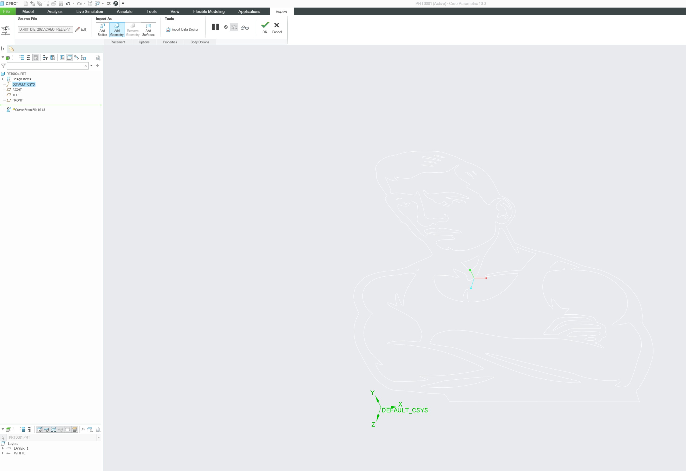
I like the crispness of "Black on White", but when I use the PROJECT button to import a DXF file in CREO, the lines of the DXF are white on white, and that tires me out really fast!
So I adopted the option with the syscol file, where I can make GEOMETRY = BLACK and retain that option, only to have a grey background to go with those white lines.
I wanted to change the white lines to another color, but I could not find the option for those anywhere...
This is what I mean -- no idea how these white curves are called, honestly.
Nov 14, 2025
07:11 PM
- Mark as New
- Bookmark
- Subscribe
- Mute
- Subscribe to RSS Feed
- Permalink
- Notify Moderator
Please log in to access translation
Nov 14, 2025
07:11 PM
EDIT: There is the possibility to use a mapping file when importing DXF data. This implies that there exists a default mapping of colors, but I am not seeing any documentation at PTC with a quick search. The system colors assignments available to the user in the GUI and via sys color files may not have control the color of imported DXF geometry.
intf2d_in_dxf_mapping_file
Specifies the mapping file for DXF or DWG import. Specify the absolute or relative path to the file. This configuration option is available as the DXF and DWG import mapping file location 2D data exchange setting in the Creo Parametric Options dialog box.
The assignment of the system colors needs to be considered in a global context; as you are finding out it can cause things to disappear or be camouflaged if not well thought out. Why are you changing the system color settings? If perhaps you are colorblind, I believe there exists some predefined sys color files to address some forms of colorblindness. If this is the case, ask here in a separate new post and open a case with PTC tech support and you will probably get some options.
How does the project function import a DXF file? I am not following that statement. Creo is functioning as designed but you have a moving target as a goal throughout this thread.
Regardless of that the imported geometry will probably use the geometry color active at the time of import; I am guessing that yours is set to white. Change it as a test to see if that is what is used for imported DXF geometry.

========================================
Involute Development, LLC
Consulting Engineers
Specialists in Creo Parametric
Involute Development, LLC
Consulting Engineers
Specialists in Creo Parametric
Nov 19, 2025
05:40 PM
- Mark as New
- Bookmark
- Subscribe
- Mute
- Subscribe to RSS Feed
- Permalink
- Notify Moderator
Please log in to access translation
Nov 19, 2025
05:40 PM
The import of the DXF starts with new creo part, change accuracy to ABSOLUTE, then pick a plane (let us say FRONT), go to the MODEL tab, click Get Data and select IMPORT. Accept default settings in the import window (or perform changes) by clicking OK, then click again OK on the IMPORT tab top ribbon.
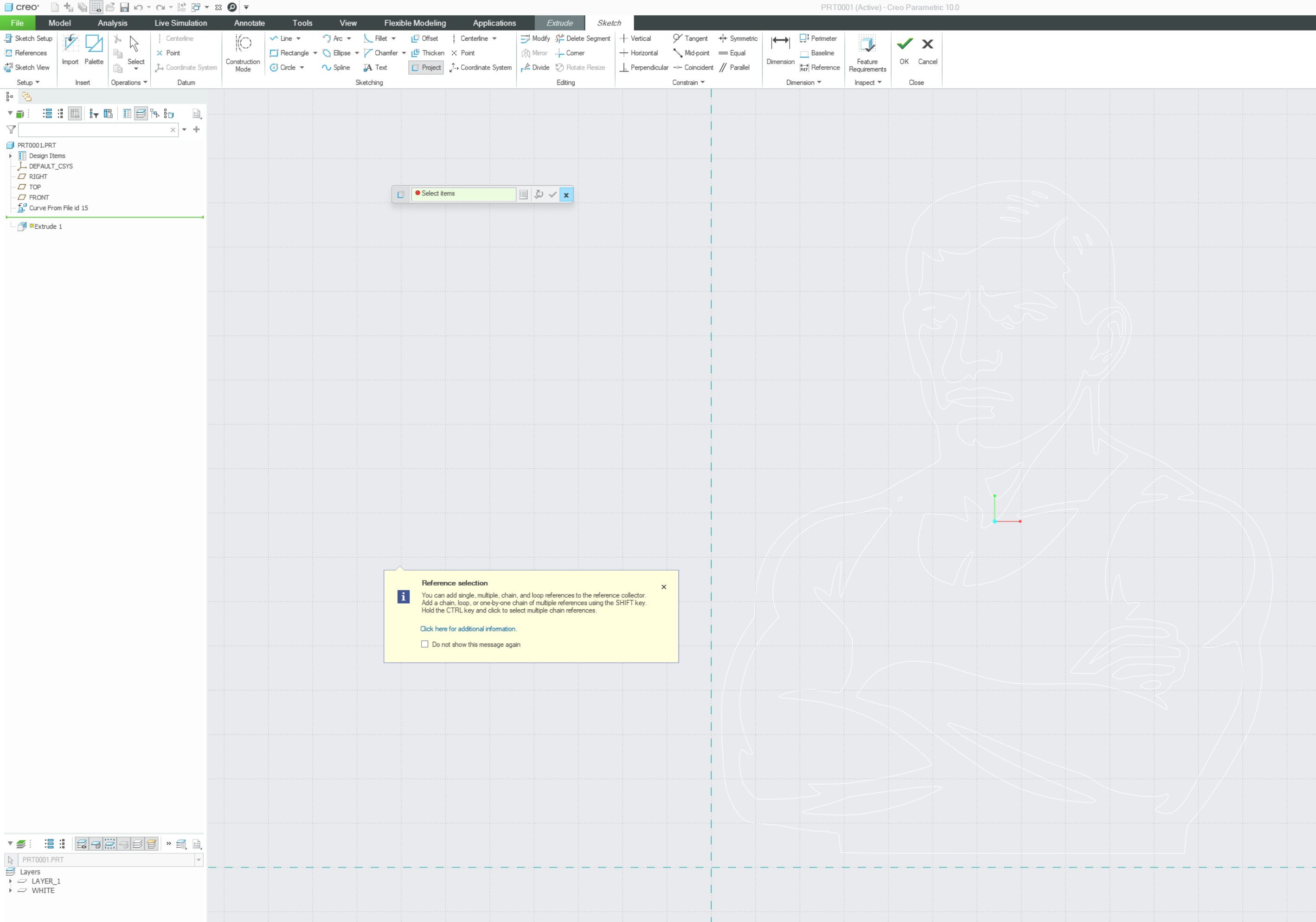
Next select again the FRONT plane, click EXTRUDE, then click PROJECT in the sketching area. Two windows should pop-up, kill the bottom large one with info, keep the SMT (Selection Mini Toolbar) top one.
Click with the mouse on any closed curve and you should see a small segment lighting up.
Press the button that looks like a listing or a book in the SMT and the CHAIN window pops up.
Change References to RULE BASED and then select rule COMPLETE LOOP and click the OK button.
You should see the whole closed loop highlighted in orange.
Click on the SMT button showing the circular green arrow (named "Create Geometry from the collected references and keep the tab open.") and now the orange curve changes to an extrude line.
Move on to the next curve and finish them all like that.
When done, press OK on the EXTRUDE ribbon.
Now change the extrude type to your needs, key in the numerical value of the extrude, and click OK on the extrude ribbon.
You should now have the extrude you wanted from the DXF file -- and this is just my way of using the import of DXF files, to get a flat extrude of a curvy subject (I convert a PNG file to get the DXF one). Other people use these DXF files in a much more sophisticated engineering manner.
And sorry for the moving target of this posting (I will stop here), I really appreciate your patience and your knowledgeable answers.
Nov 11, 2025
04:37 PM
- Mark as New
- Bookmark
- Subscribe
- Mute
- Subscribe to RSS Feed
- Permalink
- Notify Moderator
Please log in to access translation
Nov 11, 2025
04:37 PM
In the color selection screen, set Geometry (1st column) to black. You already have Shaded Edges as black (3rd column). This should cause the edges to be black all of the time, with one exception (that I know of). If you apply an appearance to the entire part (right click with paint brush active until the PRT is highlighted) , the edges (in wireframe mode) will take on the color of the part and ignore the above settings (see below). If you apply an appearance to individual surfaces, as you have done, the edges use the Geometry color when in wireframe mode. Shaded Edges color is always used when in shaded with edges mode.
This picture has an appearance applied to the entire part.

Nov 14, 2025
12:34 PM
- Mark as New
- Bookmark
- Subscribe
- Mute
- Subscribe to RSS Feed
- Permalink
- Notify Moderator
Please log in to access translation
Nov 14, 2025
12:34 PM
I have tried this and it works! But the problem now is that this change (GEOMETRY = black) is not saved by CREO 10 for permanent use (I see no SAVE button anywhere to achieve that).
As soon as I restart the CREO instance, I am back to BLUE edges in the No Hidden view.
Is it possible I may have some line in config.pro that resets the geometry setting?
Many thanks!!
Nov 14, 2025
02:47 PM
- Mark as New
- Bookmark
- Subscribe
- Mute
- Subscribe to RSS Feed
- Permalink
- Notify Moderator
Please log in to access translation
Nov 14, 2025
02:47 PM
On the System Appearance screen, bottom left, is an Export button. Save this file somewhere. I've got it stored on a network drive where I keep all of my Creo configuration files. Then add the SCL path to your config file.
system_colors_file <path>
Nov 14, 2025
06:46 PM
- Mark as New
- Bookmark
- Subscribe
- Mute
- Subscribe to RSS Feed
- Permalink
- Notify Moderator
Please log in to access translation
Nov 14, 2025
06:46 PM
The suggestion with the system_colors_file works wonderfully, thank you!!


