Turn on suggestions
Auto-suggest helps you quickly narrow down your search results by suggesting possible matches as you type.
Showing results for
Please log in to access translation
Turn on suggestions
Auto-suggest helps you quickly narrow down your search results by suggesting possible matches as you type.
Showing results for
- Community
- Creo+ and Creo Parametric
- 3D Part & Assembly Design
- Re: Helical sweep thread problem
Translate the entire conversation x
Please log in to access translation
Options
- Subscribe to RSS Feed
- Mark Topic as New
- Mark Topic as Read
- Float this Topic for Current User
- Bookmark
- Subscribe
- Mute
- Printer Friendly Page
Helical sweep thread problem
Aug 01, 2014
12:54 PM
- Mark as New
- Bookmark
- Subscribe
- Mute
- Subscribe to RSS Feed
- Permalink
- Notify Moderator
Please log in to access translation
Aug 01, 2014
12:54 PM
Helical sweep thread problem
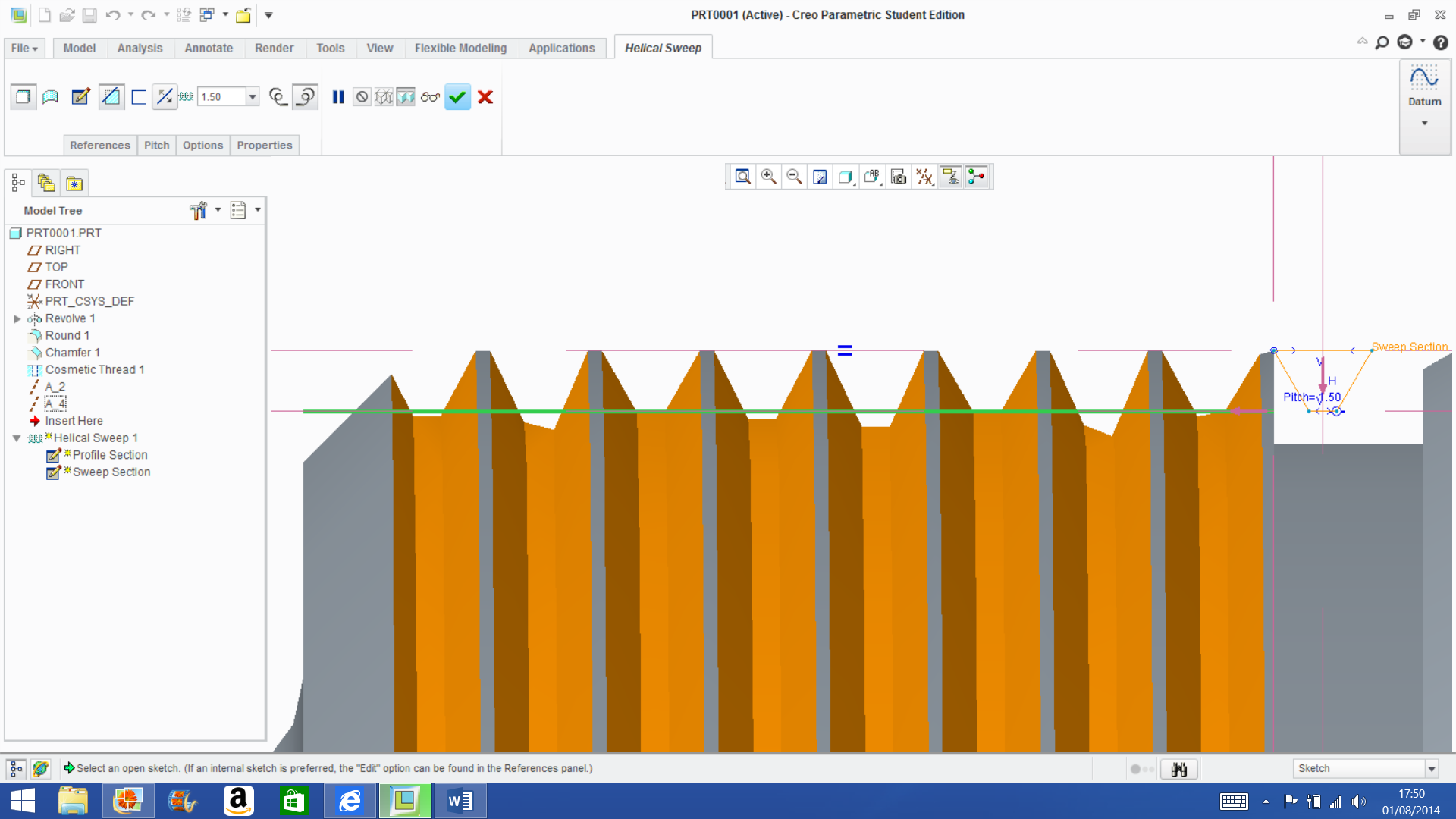
If any body could help me to find a reason for why the thread profile goes all skewed.
This thread is inactive and closed by the PTC Community Management Team. If you would like to provide a reply and re-open this thread, please notify the moderator and reference the thread. You may also use "Start a topic" button to ask a new question. Please be sure to include what version of the PTC product you are using so another community member knowledgeable about your version may be able to assist.
Solved! Go to Solution.
Labels:
- Labels:
-
General
ACCEPTED SOLUTION
Accepted Solutions
Aug 01, 2014
01:51 PM
- Mark as New
- Bookmark
- Subscribe
- Mute
- Subscribe to RSS Feed
- Permalink
- Notify Moderator
Please log in to access translation
Aug 01, 2014
01:51 PM
Make the part accuracy smaller - relative to the thread depth the pitch is almost non-existent, suggesting this is a small feature relative to the part.
15 REPLIES 15
Aug 01, 2014
12:58 PM
- Mark as New
- Bookmark
- Subscribe
- Mute
- Subscribe to RSS Feed
- Permalink
- Notify Moderator
Please log in to access translation
Aug 01, 2014
12:58 PM
Nice one 
Try making it a surface rather than a remove material and see what the origin is following.
You can post the file in the advanced editor and we can have a look.
Aug 01, 2014
02:57 PM
- Mark as New
- Bookmark
- Subscribe
- Mute
- Subscribe to RSS Feed
- Permalink
- Notify Moderator
Please log in to access translation
Aug 01, 2014
02:57 PM
Hello thanks for your offer to help really appreciate it, as whats happened here has completely baffled me.
Aug 01, 2014
03:07 PM
- Mark as New
- Bookmark
- Subscribe
- Mute
- Subscribe to RSS Feed
- Permalink
- Notify Moderator
Please log in to access translation
Aug 01, 2014
03:07 PM
I hate that! All that trouble just to have it be an education version I cannot open these.
Aug 01, 2014
03:33 PM
- Mark as New
- Bookmark
- Subscribe
- Mute
- Subscribe to RSS Feed
- Permalink
- Notify Moderator
Please log in to access translation
Aug 01, 2014
03:33 PM
Ah rats sorry thats put a spanner in the works then ay, its meant to be a standard 1.5mm pitch but on a larger diameter an OD of 293mm could that be the cause of the skewed profile?
Aug 01, 2014
03:38 PM
- Mark as New
- Bookmark
- Subscribe
- Mute
- Subscribe to RSS Feed
- Permalink
- Notify Moderator
Please log in to access translation
Aug 01, 2014
03:38 PM
As David is suggesting, it may be a graphic artifact and the part properly defined.
Changing the accuracy setting to a much lower value will show better resolution.
Aug 01, 2014
03:43 PM
- Mark as New
- Bookmark
- Subscribe
- Mute
- Subscribe to RSS Feed
- Permalink
- Notify Moderator
Please log in to access translation
Aug 01, 2014
03:43 PM
Enlarging my diameter to 12" shows similar artifacts in both the surfaces and the edges but clean right up with accuracy set to .00005 Absolute.


...its a tough thing to get use to in Creo.
Aug 01, 2014
07:08 PM
- Mark as New
- Bookmark
- Subscribe
- Mute
- Subscribe to RSS Feed
- Permalink
- Notify Moderator
Please log in to access translation
Aug 01, 2014
07:08 PM
oh right I see that's looking like what i thought it would initially turn out like!! but anyway I went into model properties and it will only let me set the accuracy as low as relative 0.0001.
Aug 01, 2014
08:16 PM
- Mark as New
- Bookmark
- Subscribe
- Mute
- Subscribe to RSS Feed
- Permalink
- Notify Moderator
Please log in to access translation
Aug 01, 2014
08:16 PM
Yea... well.. there is a few tricks to that as well.
You have to enable absolute accuracy in config.pro:
enable_absolute_accuracy yes
And then you should set the default absolute accuracy...
default_abs_accuracy .00005
Even when you do this, you will get error messages when you try to deviate from this.
This is probably the most frustrating implementation for keeping CAD efficient that I have -ever- experienced!
Aug 01, 2014
08:20 PM
- Mark as New
- Bookmark
- Subscribe
- Mute
- Subscribe to RSS Feed
- Permalink
- Notify Moderator
Please log in to access translation
Aug 01, 2014
08:20 PM
Here is the rest of them...
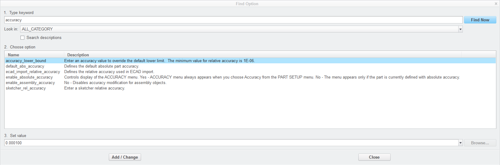
PTC recommends changing the lower bound to a very tight standard only for high precision tooling models.
Personally, I think PTC should just make is "perfect" to start with
Aug 02, 2014
11:41 AM
- Mark as New
- Bookmark
- Subscribe
- Mute
- Subscribe to RSS Feed
- Permalink
- Notify Moderator
Please log in to access translation
Aug 02, 2014
11:41 AM
Well that weren't half a hassle!! but after doing what you said this is the result hoorah!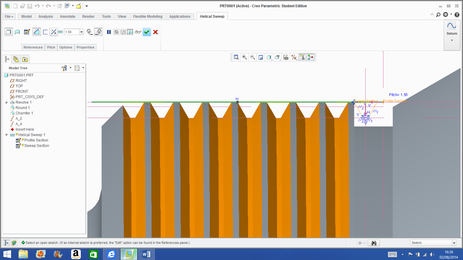
Aug 02, 2014
01:41 PM
- Mark as New
- Bookmark
- Subscribe
- Mute
- Subscribe to RSS Feed
- Permalink
- Notify Moderator
Please log in to access translation
Aug 02, 2014
01:41 PM
Congrats! You might mark David's answer as correct.
Aug 01, 2014
01:51 PM
- Mark as New
- Bookmark
- Subscribe
- Mute
- Subscribe to RSS Feed
- Permalink
- Notify Moderator
Please log in to access translation
Aug 01, 2014
01:51 PM
Make the part accuracy smaller - relative to the thread depth the pitch is almost non-existent, suggesting this is a small feature relative to the part.
Aug 01, 2014
02:01 PM
- Mark as New
- Bookmark
- Subscribe
- Mute
- Subscribe to RSS Feed
- Permalink
- Notify Moderator
Please log in to access translation
Aug 01, 2014
02:01 PM
The pitch is 1.5 so it is not that small.
There is something wrong with a reference.
Never had a helical sweep do that to me.
Aug 01, 2014
02:56 PM
- Mark as New
- Bookmark
- Subscribe
- Mute
- Subscribe to RSS Feed
- Permalink
- Notify Moderator
Please log in to access translation
Aug 01, 2014
02:56 PM
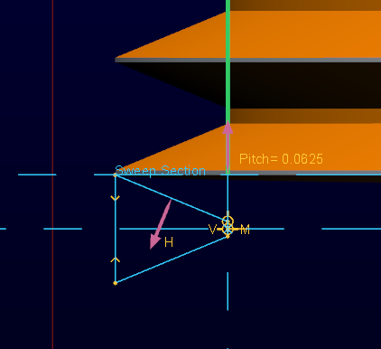
Pitch as a function of the thread diameter. The threads are almost vertical - 1:50 or less.
This looks like the advance of a microscope thread or small ratio of advance to diameter.
Aug 01, 2014
03:20 PM
- Mark as New
- Bookmark
- Subscribe
- Mute
- Subscribe to RSS Feed
- Permalink
- Notify Moderator
Please log in to access translation
Aug 01, 2014
03:20 PM
I am going to suggest there is something strange with the reference on the OD of the part. In this one, I use a vertex (end of arc, edge) to align the OD. This is a 3" OD with a 1/16th" pitch.