
Turn on suggestions
Auto-suggest helps you quickly narrow down your search results by suggesting possible matches as you type.
Showing results for
Please log in to access translation
Turn on suggestions
Auto-suggest helps you quickly narrow down your search results by suggesting possible matches as you type.
Showing results for
Community Tip - If community subscription notifications are filling up your inbox you can set up a daily digest and get all your notifications in a single email. X
- Community
- Creo+ and Creo Parametric
- 3D Part & Assembly Design
- Re: Help for creating an annotation, driven dimens...
Translate the entire conversation x
Please log in to access translation
Options
- Subscribe to RSS Feed
- Mark Topic as New
- Mark Topic as Read
- Float this Topic for Current User
- Bookmark
- Subscribe
- Mute
- Printer Friendly Page
Help for creating an annotation, driven dimension on diameter
Feb 21, 2022
09:26 AM
- Mark as New
- Bookmark
- Subscribe
- Mute
- Subscribe to RSS Feed
- Permalink
- Notify Moderator
Please log in to access translation
Feb 21, 2022
09:26 AM
Help for creating an annotation, driven dimension on diameter
Hello,
I would like to know how can I create a dimension driven (annotation) on a diameter whose annotation plane is parallel and passing through the axis of revolution?
This is what i can currently do with creo 7:
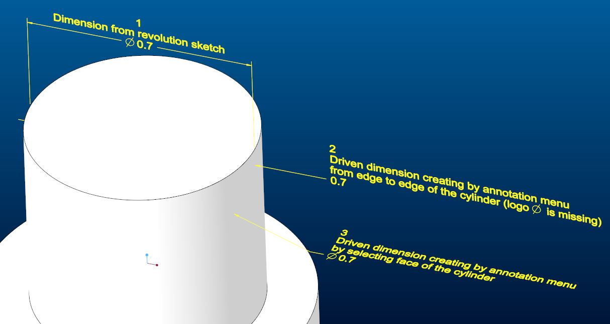
I can show dimension from revolution sketch [see dim 1 in the print screen1] : orientation is ok => I want to reproduce the same result with a dimension driven via annotation menu
If i create annotation dimension on the front annotation plane by selecting face of the cylinder, creo desn't want to proceed. I can only select edges of the cylinder but creo see that dim like a linear dim (not diameter). So orientation is ok [see dim 2 in the print screen1].
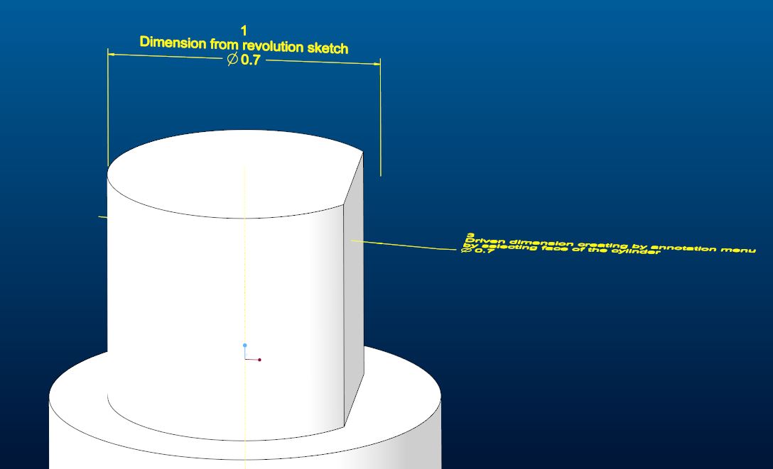
if I add a flat on the cylinder, the driven dim disappears and it is impossible to show it or re-create this dimension because of the flat. [see print screen2] => that's why i don't want to use this way.
If i really want to create a dimension by selecting the face (not edges) of the cylinder, first I have to use the top annotation plane and the annotation is created like diameter driven dimension [see dim 3 in the print screen1]. But orientation of the diameter is not the one i want and it's impossible to change it corresponding of front plane.
Can you help me find a way to create the annotation I need?
Regards,
Arnaud
Solved! Go to Solution.
Labels:
- Labels:
-
2D Drawing
-
General
-
MBD_GD&T
ACCEPTED SOLUTION
Accepted Solutions
Mar 01, 2022
05:13 AM
- Mark as New
- Bookmark
- Subscribe
- Mute
- Subscribe to RSS Feed
- Permalink
- Notify Moderator
Please log in to access translation
Mar 01, 2022
05:13 AM
Hello @pausob
This is a very good question, and complicates significantly the investigation of this given use case. In few words:
- This occurs because all parent references are lost for the impacted Annotation Element in such situations
- No other choice therefore to:
- Create new references (if not available in geometry, like in this use case)
- Redefine parent references of the impacted Annotation Element afterwards
I registered for you a little movie reproducing the issue first, and then providing guidance on "how to resolve" in similar situations.
Hope this helps,
Regards,
Serge
10 REPLIES 10
Feb 22, 2022
03:48 AM
- Mark as New
- Bookmark
- Subscribe
- Mute
- Subscribe to RSS Feed
- Permalink
- Notify Moderator
Please log in to access translation
Feb 22, 2022
03:48 AM
I'm not totally sure why you want to make a driven dimension when you can simply show the driving dimension in an annotation state, but one way is to make your sketch of the cross-section of revolution "external" and then annotate this sketch. You'll need an extra datum point in it so that you can dimension the diameter by making a linear dimension between this point and the "edge" of the cylinder (the vertical line in the sketch), and you'll have to add the Ø symbol by editing the dimension text:

Then after creating flats, etc.., your driven dimension will not fail because it's not tied to any solid geometry:

Feb 23, 2022
10:46 AM
- Mark as New
- Bookmark
- Subscribe
- Mute
- Subscribe to RSS Feed
- Permalink
- Notify Moderator
Please log in to access translation
Feb 23, 2022
10:46 AM
Thanks for you're reply,
I prefer not create a sketch dedicated to dimensioning. I have to doing all the dimensioning work with the annotation menu (or via an annotation function)
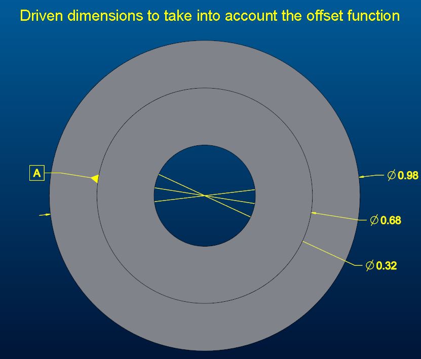
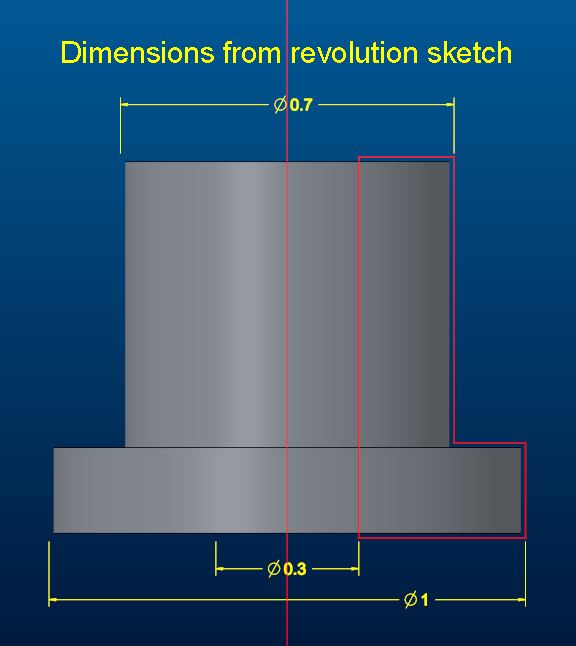
I add in this post a second example which shows that it's not possible to reuse the sketch of the revolve function. Please see print screen [revolution1] + [relovution2]
Here we have an inherited part in which we created an offset in order to remove material everywhere in a function (which is useful for complex parts).
If we display the dimensions of the inherited part, it is not correct because it dosen't take into account the offset . It is therefore necessary to go through annotations to be able to set the dimensions of the part after offset.
It is in this kind of case where I cannot reorient my dimensions on the parallel plane of the axis of revolution
Feb 23, 2022
08:45 PM
- Mark as New
- Bookmark
- Subscribe
- Mute
- Subscribe to RSS Feed
- Permalink
- Notify Moderator
Please log in to access translation
Feb 23, 2022
08:45 PM
Yes, I see the difficulty in trying to dimension cylindrical surfaces on the annotation plane that their axis of revolution lies upon... I don't know the trick.
Instead of sketches, you can attach datum points to the surfaces and dimension to these "construction" points...
Or maybe you could make a cross-section and use its lines to construct the annotation dimension... You can turn off the hatching to make it look better:

Feb 28, 2022
07:49 AM
- Mark as New
- Bookmark
- Subscribe
- Mute
- Subscribe to RSS Feed
- Permalink
- Notify Moderator
Please log in to access translation
Feb 28, 2022
07:49 AM
Hello @ArnaudGOELZER
In such situation, in order to reconfigure your Annotation Element in the good orientation, you need to proceed as follows:
- Create first a "Good Orientation" and Save it
- Then use Change Orientation capability with Right Click on impacted Annotation Element
In order to grant probably a better understanding of what I mean, I illustrated this approach for you in the little movie at the end of this post.
Hope this helps,
Regards,
Serge
Feb 28, 2022
02:02 PM
- Mark as New
- Bookmark
- Subscribe
- Mute
- Subscribe to RSS Feed
- Permalink
- Notify Moderator
Please log in to access translation
Feb 28, 2022
02:02 PM
Thanks for the video! Out of curiosity, what if you wanted the dimension to be aligned with the "right" plane, so as to avoid the flats altogether? Would you simply change the angle of your slanted plane to 90° and it would work?
FYI, this is what happens on my system (Creo 4):
Cylinder diameter annotated as a linear dimension between vertices of the half-cylinder surface, on FRONT plane:

After flats are put in:

After changing the orientation of the annotation to the slanted plane:

(And if I change the orientation of this annotation to the RIGHT plane, then it reads 0... Whether or not the flats are in the model)
Mar 01, 2022
05:13 AM
- Mark as New
- Bookmark
- Subscribe
- Mute
- Subscribe to RSS Feed
- Permalink
- Notify Moderator
Please log in to access translation
Mar 01, 2022
05:13 AM
Hello @pausob
This is a very good question, and complicates significantly the investigation of this given use case. In few words:
- This occurs because all parent references are lost for the impacted Annotation Element in such situations
- No other choice therefore to:
- Create new references (if not available in geometry, like in this use case)
- Redefine parent references of the impacted Annotation Element afterwards
I registered for you a little movie reproducing the issue first, and then providing guidance on "how to resolve" in similar situations.
Hope this helps,
Regards,
Serge
Mar 01, 2022
04:23 PM
- Mark as New
- Bookmark
- Subscribe
- Mute
- Subscribe to RSS Feed
- Permalink
- Notify Moderator
Please log in to access translation
Mar 01, 2022
04:23 PM
Yes, I can see how you used datum points to anchor the annotation dimension's extension lines to the entity of interest. But how come you didn't have to do this in your first video in the thread?
Also, just to clarify: if you use the top annotation plane, then you can get a Ø style annotation dimension immediately - as the system allows you to select the circular edge; but there is no way to re-orient such dimension onto the front or right planes and convert it to a linear-style dimension?
Mar 09, 2022
08:16 AM
- Mark as New
- Bookmark
- Subscribe
- Mute
- Subscribe to RSS Feed
- Permalink
- Notify Moderator
Please log in to access translation
Mar 09, 2022
08:16 AM
Thank you for taking the time to explain your annotation methodologies.
After testing I notice that if the dimension is linear, even adding the diameter symbol, creo does not understand it as a diameter and the positioning of the datum tag is not correct. please watch "diameter_KO".
If I place a diameter driven dimension (annotation), like I wanted to do from the start, the datum tag is positioned correctly. Please watch "diameter_ok"
The problem that will follow is to reorient this dimension on a plane parallel to the axis of revolution
Mar 09, 2022
09:03 AM
- Mark as New
- Bookmark
- Subscribe
- Mute
- Subscribe to RSS Feed
- Permalink
- Notify Moderator
Please log in to access translation
Mar 09, 2022
09:03 AM
Hello @ArnaudGOELZER
For the Diameter_KO use case, the DFS has to be placed on Witness Line of the dimenison, and not on the Dimenion.
=> Refer to attached movie reproducing your issue first, and then resolving it later on, for a better understanding.
Hello @pausob
In the first movie of this topic, the unique failed reference was not shown in the movie but was present. The presence of at least one still working and effective reference allowed me to fix the original use case without redefining references, but "in the rule of the art", you're right, it would have been for sure better to have resepcify a good second reference (the one which was missing after extrude on only one part of the cylinder) to be in a clean situation.
Regarding your question, How to convert a diameter dimension to a linear dimension displayed in a different orientation plane? (Originally produced as "diameter dimension" as expected, due to the correct orientation plane being parallel to the skecth diameter dimension orientation):
- If this is possible to convert it from diameter dimension to linear dimension
- It is however not possible to Change Orientation Plane to a plane being non-parallel of the one where sketch diameter dimension exists (current limitation)
Refer to second movie for a better understanding of what I mean.
Regards,
Serge
Mar 18, 2022
07:25 AM
- Mark as New
- Bookmark
- Subscribe
- Mute
- Subscribe to RSS Feed
- Permalink
- Notify Moderator
Please log in to access translation
Mar 18, 2022
07:25 AM
Thanks for suggesting a workaround.
I notice that it requires a lot of actions to be carried out before reaching the result.
Of course, this action is useful only if it is impossible to reuse the dimension of the sketch.
I think a creo improvement would be desirable in this case to save time and make this maneuver more intuitive.
I think that if it was possible to directly create the annotation as a diameter on the FRONT or BACK annotation plane (works correctly today) but with the additional possibility of redirecting this dimension on the TOP or RIGHT annotation planes would be really interesting. (behavior similar to the diameter dimension created in a sketch)
Regards,
Arnaud


