
Turn on suggestions
Auto-suggest helps you quickly narrow down your search results by suggesting possible matches as you type.
Showing results for
Please log in to access translation
Turn on suggestions
Auto-suggest helps you quickly narrow down your search results by suggesting possible matches as you type.
Showing results for
Community Tip - Did you know you can set a signature that will be added to all your posts? Set it here! X
- Community
- Creo+ and Creo Parametric
- 3D Part & Assembly Design
- How do you hide construction lines in drawing
Translate the entire conversation x
Please log in to access translation
Options
- Subscribe to RSS Feed
- Mark Topic as New
- Mark Topic as Read
- Float this Topic for Current User
- Bookmark
- Subscribe
- Mute
- Printer Friendly Page
How do you hide construction lines in drawing
Nov 21, 2016
09:38 AM
- Mark as New
- Bookmark
- Subscribe
- Mute
- Subscribe to RSS Feed
- Permalink
- Notify Moderator
Please log in to access translation
Nov 21, 2016
09:38 AM
How do you hide construction lines in drawing
I need to have construction lines to get intersections and dimension placements on a drawing but I can't seem to find how this is hidden.
I do however have a few solid lines and arcs that I would want displayed on the drawing.
Is there a way to filter by construction entities and blank these on a drawing?
This thread is inactive and closed by the PTC Community Management Team. If you would like to provide a reply and re-open this thread, please notify the moderator and reference the thread. You may also use "Start a topic" button to ask a new question. Please be sure to include what version of the PTC product you are using so another community member knowledgeable about your version may be able to assist.
Solved! Go to Solution.
Labels:
- Labels:
-
2D Drawing
ACCEPTED SOLUTION
Accepted Solutions
Nov 22, 2016
02:52 AM
- Mark as New
- Bookmark
- Subscribe
- Mute
- Subscribe to RSS Feed
- Permalink
- Notify Moderator
Please log in to access translation
Nov 22, 2016
02:52 AM
Hi,
you published picture of your drawing. Unfortunately I do not understand how construction lines were created. Are they draft entities created in the drawing ? If this is true, then hiding them using layer is the only way I know.
MH
Martin Hanák
20 REPLIES 20
Nov 21, 2016
01:46 PM
- Mark as New
- Bookmark
- Subscribe
- Mute
- Subscribe to RSS Feed
- Permalink
- Notify Moderator
Please log in to access translation
Nov 21, 2016
01:46 PM
Hi,
can you upload some example data and pictures showing what you want to hide ?
MH
Martin Hanák
Nov 21, 2016
02:16 PM
- Mark as New
- Bookmark
- Subscribe
- Mute
- Subscribe to RSS Feed
- Permalink
- Notify Moderator
Please log in to access translation
Nov 21, 2016
02:16 PM
Martin
Here is a view of the type of entities I would like to hide. See the type arrowed in green.
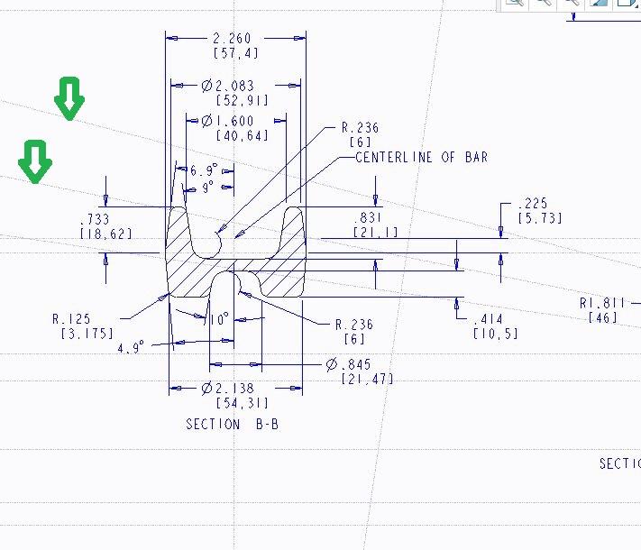
Since my post I have discovered that I can make a new layer to the specified entity type and specifically hide this.
Is there an easier way? I would prefer to select all of a type and just right click hide, but that isn't possible that I can see.
Nov 22, 2016
02:52 AM
- Mark as New
- Bookmark
- Subscribe
- Mute
- Subscribe to RSS Feed
- Permalink
- Notify Moderator
Please log in to access translation
Nov 22, 2016
02:52 AM
Hi,
you published picture of your drawing. Unfortunately I do not understand how construction lines were created. Are they draft entities created in the drawing ? If this is true, then hiding them using layer is the only way I know.
MH
Martin Hanák
Nov 22, 2016
07:12 AM
- Mark as New
- Bookmark
- Subscribe
- Mute
- Subscribe to RSS Feed
- Permalink
- Notify Moderator
Please log in to access translation
Nov 22, 2016
07:12 AM
Yes these were sketch entities built on the drawing.
It is a shame that layers is the only way to remove these entities. I didn't even see this as possible until just after I posted my question.
Since these entities are the only way to build many dimensions and it isn't part of the model itself it is a shame that they don't hide easier.
Nov 22, 2016
12:17 PM
- Mark as New
- Bookmark
- Subscribe
- Mute
- Subscribe to RSS Feed
- Permalink
- Notify Moderator
Please log in to access translation
Nov 22, 2016
12:17 PM
I'm curious what you feel would be easier? You want them to continue to exist, and not to be shown, and layers are the usual way of doing that. Presuming you made a default layer for construction entities (or make a layer by rule or by mass-selecting with Find dialog or drawing tree if you hadn't yet), hiding them is quickly done.
I'm interested in any suggestions that might improve the product, or possibly just the way it's presented -- it's a large and complex program, and it's hard for a person to know all the settings that might optimize their workflows.
Nov 22, 2016
01:07 PM
- Mark as New
- Bookmark
- Subscribe
- Mute
- Subscribe to RSS Feed
- Permalink
- Notify Moderator
Please log in to access translation
Nov 22, 2016
01:07 PM
Matthew,
Thank you for asking.
I guess my initial quandary was that I didn't see an obvious way of turning the construction lines off.
There were layers shown for each individual drawing view but even though I could select the construction entities within each view there was no option to turn these off.
I filter selected all of the construction entities and was hoping they would blank by a right click option but it wasn't there.
Adding to the confusion I was finding that my construction entities moved around from where they were on the view. As Kevin suggests it would be best if I didn't need to use construction entities and that in most cases I should be able to get dimensions without it. This may be true but at this point I haven't learned the way to do this.
It would really be nice if you could toggle hide construction entities. There are cases when I do want to see a line or arc, but anything that has only a dimension construction purpose it would be nice to hide the clutter with one button push.
This wouldn't be the highest wish on my list (that would be allowing showing drawing decimal places that would be independent of the model decimal places). Now that I know I can save off the construction entities on a layer I would just need to define this in each drawing. If however this was changed to toggle on and off it would be used all of the time in my application.
Nov 22, 2016
01:25 PM
- Mark as New
- Bookmark
- Subscribe
- Mute
- Subscribe to RSS Feed
- Permalink
- Notify Moderator
Please log in to access translation
Nov 22, 2016
01:25 PM
Thanks for the explanation. I agree that in the case of multiple views with view-dependent layer settings, it'd be more cumbersome to turn them on/off (though I suppose in that case, you'd probably only want to turn them on/off for the relevant view). So, looking for something along the lines of the environment > entity display toggles? Could post it in the Ideas section and see what support it gathers.
I think that Kevin may be right that the use of construction entities here isn't likely the right way to get what you want done. Unless sketch parametrically, sketched entities aren't going to update when your view changes, and this could lead to misleading documentation of the model. Perhaps it would be good to open another discussion (forum thread or perhaps an SPR) on the topic of the sort of dimension you wish to make that is proving difficult.
Nov 22, 2016
11:30 AM
- Mark as New
- Bookmark
- Subscribe
- Mute
- Subscribe to RSS Feed
- Permalink
- Notify Moderator
Please log in to access translation
Nov 22, 2016
11:30 AM
I normally try not to use drawing sketch entities on drawings as they don't always maintain their relationship to the part as things change.
For a center line, I would add a centerline to the model. Datum planes in the model can be used for a difficult references. Dimensions can also be attached to drawing and model entities, surfaces. midpoint, centers, and intersections.
I can not determine exactly what all of your dimensions are attached to, but believe all could be made without drawing sketch references.
There is always more to learn in Creo.
Nov 22, 2016
12:02 PM
- Mark as New
- Bookmark
- Subscribe
- Mute
- Subscribe to RSS Feed
- Permalink
- Notify Moderator
Please log in to access translation
Nov 22, 2016
12:02 PM
Thank you Kevin,
I am very much an amateur with drawings. As I was making the drawing it didn't seem that I could select very much of the part itself. I can attest that the sketch lines do move around and aren't very trustworthy.
I will certainly test out what you have suggested. It would be nice not to be so reliant on entities that might not move with the movement of a view re-positioning.
Dec 07, 2016
07:42 AM
- Mark as New
- Bookmark
- Subscribe
- Mute
- Subscribe to RSS Feed
- Permalink
- Notify Moderator
Please log in to access translation
Dec 07, 2016
07:42 AM
This is in response to the question of construction lines not moving when views are repositioned. If you select the line and right click then select the "relate to view" option then select the view that you want it to follow, it will then move as the view is repositioned. Or maybe I'm not understanding the problem?
Dec 07, 2016
08:12 AM
- Mark as New
- Bookmark
- Subscribe
- Mute
- Subscribe to RSS Feed
- Permalink
- Notify Moderator
Please log in to access translation
Dec 07, 2016
08:12 AM
Yes,
That is quite helpful.
Being new to the drawing process however it is difficult to remember the step of freezing the lines.
Thank you for the reminder.
I still am trying to find ways to where things will come in with enough entities to fully dimension the print.
Dec 07, 2016
08:27 AM
- Mark as New
- Bookmark
- Subscribe
- Mute
- Subscribe to RSS Feed
- Permalink
- Notify Moderator
Please log in to access translation
Dec 07, 2016
08:27 AM
Have you used "show model annotations"? That should bring in all dimensions that were used to create the model. You can then select the dimensions, axis, planes etc. that you want to show. I don't often use it because of my poor modeling skills I end up with too many dimensions and it floods the drawing, making it hard to find the needed dimension. But worth a try?
Dec 07, 2016
09:37 AM
- Mark as New
- Bookmark
- Subscribe
- Mute
- Subscribe to RSS Feed
- Permalink
- Notify Moderator
Please log in to access translation
Dec 07, 2016
09:37 AM
I have observed the results of "show model annotations"; unfortunately in our case the models are too complex in curvature to show up decent dimensions. It would be nice if only sketch dimensions showed up.
Dec 07, 2016
11:12 AM
- Mark as New
- Bookmark
- Subscribe
- Mute
- Subscribe to RSS Feed
- Permalink
- Notify Moderator
Please log in to access translation
Dec 07, 2016
11:12 AM
Agreed. That's also why I seldom use it. When I try it typically it totally floods the drawing with dimensions to thick they can't be found. But there has been a few times I've been unable to dimension as I wanted and was able to find the dimension with this method.
Dec 07, 2016
11:18 AM
- Mark as New
- Bookmark
- Subscribe
- Mute
- Subscribe to RSS Feed
- Permalink
- Notify Moderator
Please log in to access translation
Dec 07, 2016
11:18 AM
One trick to showing dimensions when there are too many is to show by feature using a query select or selecting in the tree rather than selecting the entire view.
There is always more to learn in Creo.
Dec 07, 2016
12:29 PM
- Mark as New
- Bookmark
- Subscribe
- Mute
- Subscribe to RSS Feed
- Permalink
- Notify Moderator
Please log in to access translation
Dec 07, 2016
12:29 PM
That sounds interesting. I'll have to try it next time I come across it. Thank you.
Dec 05, 2016
02:07 PM
- Mark as New
- Bookmark
- Subscribe
- Mute
- Subscribe to RSS Feed
- Permalink
- Notify Moderator
Please log in to access translation
Dec 05, 2016
02:07 PM
Kevin:
Today I started a new drawing. With some searching I was able to discern how to display datum axis with views so I know this won't move.
Unfortunately I have a large arcs which displays as segments of splines which looks like a construction entities would be necessary.
This originally would have been an arc, but through an intersection on the model it no longer displays as an arc.
There appear to be work arounds for different entities to display without need of construction entities; would this be an exception?
Dec 05, 2016
02:21 PM
- Mark as New
- Bookmark
- Subscribe
- Mute
- Subscribe to RSS Feed
- Permalink
- Notify Moderator
Please log in to access translation
Dec 05, 2016
02:21 PM
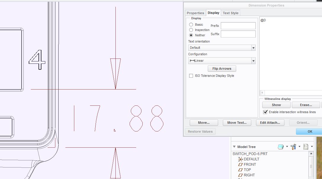
Not sure what you are trying to do. I will assume you are dimensioning. If you are dimensioning to an intersection, after placing the dimension open the properties dialog box and on the Display tab check the box for "Enable intersection witness lines" to show parametric witness lines. The ends can also be adjusted after you close the properties. This should work for most intersections.
There is always more to learn in Creo.
Dec 05, 2016
02:52 PM
- Mark as New
- Bookmark
- Subscribe
- Mute
- Subscribe to RSS Feed
- Permalink
- Notify Moderator
Please log in to access translation
Dec 05, 2016
02:52 PM
What I am looking for would be a radius dimension along the spline. Since this is seen as a spline there doesn't appear to be a way to build the dimension without making a construction entity. Highlighted below is the area I need the large radii.
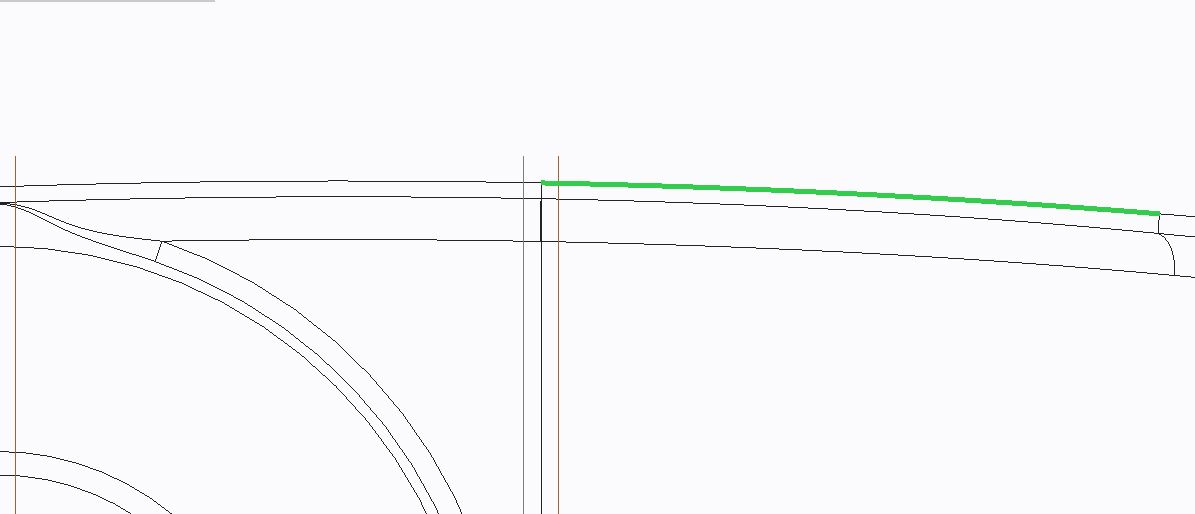
In our other CAD system it was possible to get a radii dimension off of a spline, the number would vary along the spline. I don't see that as possible but it would save a lot of trouble if it were possible.
Dec 05, 2016
03:54 PM
- Mark as New
- Bookmark
- Subscribe
- Mute
- Subscribe to RSS Feed
- Permalink
- Notify Moderator
Please log in to access translation
Dec 05, 2016
03:54 PM
What I have done in the past to "fake" a dimension when it can't be shown or created is make a sketch or a cosmetic sketch in the model and hide it on a layer so that I can show the dimension and keep it parametric to the part.
If the radius was created in the view plane orientation there should be a way to show it.
If the radius is equal to another radius in the sketch the dimension can only be shown once. Deleting the equal constraint and making the new dimension equal to the old one by relation (e.g. enter d7 instead of 25.50 for the dimension) will give you another dimension to show.
Using the round tool gives you one dimension to show per Set. Use multiple sets or multiple features to get multiple shown dimensions.
These dimensions can be shown even if modified by other features making them splines. The arrow head may be slightly detached from the line.
There is always more to learn in Creo.


