
Turn on suggestions
Auto-suggest helps you quickly narrow down your search results by suggesting possible matches as you type.
Showing results for
Please log in to access translation
Turn on suggestions
Auto-suggest helps you quickly narrow down your search results by suggesting possible matches as you type.
Showing results for
Community Tip - Learn all about the Community Ranking System, a fun gamification element of the PTC Community. X
- Community
- Creo+ and Creo Parametric
- 3D Part & Assembly Design
- Re: Line weights and PDF files
Translate the entire conversation x
Please log in to access translation
Options
- Subscribe to RSS Feed
- Mark Topic as New
- Mark Topic as Read
- Float this Topic for Current User
- Bookmark
- Subscribe
- Mute
- Printer Friendly Page
Line weights and PDF files
May 09, 2013
09:09 PM
- Mark as New
- Bookmark
- Subscribe
- Mute
- Subscribe to RSS Feed
- Permalink
- Notify Moderator
Please log in to access translation
May 09, 2013
09:09 PM
Line weights and PDF files
I looked around for a solution but to no avail. Changing the config.pro pen_line_weight has no effect on my drawings. I tried using a pen table but did not get the results I was looking for. Using the pen table (I think) means that all geometry lines printed with pen 1 will all have the same line thickness. This means that, not only geometry lines but drawing border lines will be the same thickness... which I don't want.
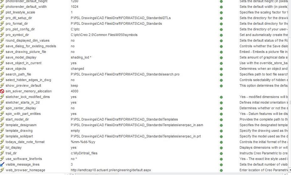
PTC TPI 117022 suggests changing the line weight config.pro option which will not overwrite user-defined thickness. I have made sure that I have no table.prt files, the option to use pen tables is removed from config.pro and the option to use pen tables for PDF is removed.
Lines that have user-defined thickness print with correct weight but no matter what number I put in to the pen 1 and pen 2 options, geometry and dimension lines are not affected (too thick and too thin respectively).
Currently using Creo2.0 m50. What am I missing?
Thanks all.
Solved! Go to Solution.
Labels:
- Labels:
-
2D Drawing
- Tags:
ACCEPTED SOLUTION
Accepted Solutions
Jan 11, 2022
10:50 AM
- Mark as New
- Bookmark
- Subscribe
- Mute
- Subscribe to RSS Feed
- Permalink
- Notify Moderator
Please log in to access translation
Jan 11, 2022
10:50 AM
To close this community thread on Line weights and PDF files
Summary of the exchanges and list of solutions:
- If no Pen Table is used, the line weights will be set "as displayed" on the screen in the PDF.
- pen#_line_weight configuration options won’t affect the export (only plotters)

- In order to control the line thickness, you will need to use a Pen Table as explained in article CS25880, also some examples are provided in the different replies.
- Then each line with a given System/Entity color (eg Geometry, Curve, etc) will get the properties defined in the corresponding pen.
- User-defined colors will go to pen 1
- The thickness defined on screen will be preserved if not explicitly defined on the pen, otherwise it will be overridden.
- Therefore you cannot specify a new default thickness for objects assigned to the same pen and keep the manually entered weight in drawing for some of those lines.
- Possible workaround:
- Set lines with a defined weight to a different system/entity color that is assigned to a pen with no thickness argument.
- If you need to specify a user defined color to those lines you may want to move the other system/entity colors (eg Geometry "drawing_color", Datum "datum_color", etc) that go to pen 1 to another pen (eg 4), and keep pen 1 for user defined color only.
- For example only setting a black color as output:
pen 1 color 0.0 0.0 0.0
...
pen 4 thickness .035 cm; color 0.0 0.0 0.0; drawing_color; datum_color
30 REPLIES 30
May 09, 2013
09:51 PM
- Mark as New
- Bookmark
- Subscribe
- Mute
- Subscribe to RSS Feed
- Permalink
- Notify Moderator
Please log in to access translation
May 09, 2013
09:51 PM
Hi Tony,
I went through this starting in WF4 and finally finished it a couple of years later in WF5 (now Creo Elements/Pro 5). Help was nebulous. In essence we had always used the old config pen weight commands per colour and I was concerned with making readable PDFs from within WF5/Creo.
With a lot of help from our VAR I got there in the end. The key to the solution was to delete or remark out the lineweights in the config and have the config use pdfpentable instead. We tried many lineweights in the pdfpentable till we got what worked to make clear PDFs for screen and print and especially checking A3 drawings being printed at A4. We make almost all of our drawings as A3 with some at A4 and just a few at A2 or A1. Thus our settings are biased in favour of A3 but these do work across those other sizes even when we tried reducing an A1 to A4 as a printout then photocopying that and copying the copy for five times (we did this test with all sizes).
Had to redo our formats and also our templates which call these up but that was OK as there were other aspects we wanted to improve there as well such as making the title block 100% auto-completed from the 3D model (which we hold as our master).
We also changed over to Truetype fonts for this PDF process (we picked Arial Narrow which is arialn from the windows font directory). It was a long and tedious process with three steps forward and two steps back most days but victory in the end. This also meant changing the symbols we had already made in our library with newer versions.
Kinda busy at the moment but can give you details over the next few days if you want.
Regards, Brent
May 10, 2013
11:54 AM
- Mark as New
- Bookmark
- Subscribe
- Mute
- Subscribe to RSS Feed
- Permalink
- Notify Moderator
Please log in to access translation
May 10, 2013
11:54 AM
Thanks Brent. I'm attempting to do the same thing you did - trying to improve our formats and templates. Not sure what is "pdfpentable". Perhaps this is the config.pro setting I should be using, but I can't seem to locate it in the config editor.
The option"pdf_use_pentable" for pen 1 will change ALL lines including my drawing border meaning that geo lines will be very thick (like the border) or the border will be very thin (like the geometry lines). In other words, using a pen table will overwrite my user-defined line thicknesses.
My current work-around is to use the default line settings (user defined border), then after saving as PDF, open with Illustrator and correct the line weights and other stuff that looks OK in Creo but not as a PDF. Such as, centering numbers in balloons and moving drawing and table borders that seem to shift and text that gets out of position. What a hassle.
Thanks for your help.
May 10, 2013
12:19 PM
- Mark as New
- Bookmark
- Subscribe
- Mute
- Subscribe to RSS Feed
- Permalink
- Notify Moderator
Please log in to access translation
May 10, 2013
12:19 PM
If the borders is the biggest problem, you can assign a line style from any of the other pentable options, for instance, change the linestyle in the format to Datums and assign a unique pen to this style. Now you have a separation between the border and the geometry when printing the drawing.
May 10, 2013
12:24 PM
- Mark as New
- Bookmark
- Subscribe
- Mute
- Subscribe to RSS Feed
- Permalink
- Notify Moderator
Please log in to access translation
May 10, 2013
12:24 PM
I had a lot of trouble getting PDF's to plot correctly, too. Here is what I ended up doing:
Put the following lines in your config.pro file:
pdf_use_pentable yes
use_8_plotter_pens yes
pen_table_file T:\Engineer\Library_Proe\6_Creo2_System_Files\config\Plot\pen_table_pdf.pnt
"T:\Engineer\Library_Proe\6_Creo2_System_Files\config\Plot" is my path to the "pen_table_pdf.pnt" file.
The pen_table_pdf.pnt is just a text file that contains the following lines:
pen 1 thickness 0.005 cm
pen 2 thickness 0.005 cm
pen 3 thickness 0.005 cm
pen 4 thickness 0.005 cm
pen 5 thickness 0.005 cm
pen 6 thickness 0.005 cm
pen 7 thickness 0.005 cm
pen 8 thickness 0.005 cm
For plotting to the plotter or printer, we use the default MS_PRINT_MGR. The ms_print_mgr.pcf file has a line that calls for the pen_table_ms_print_mgr.pnt pen table file. Make sure to use the correct paths to your file locations.
Hope this helps,
Rick Z.
Sep 11, 2013
11:59 AM
- Mark as New
- Bookmark
- Subscribe
- Mute
- Subscribe to RSS Feed
- Permalink
- Notify Moderator
Please log in to access translation
Sep 11, 2013
11:59 AM
Hi Rick,
I'm still not having any luck. My problem is my text appears bold after selecting "Stroke All Fonts" (to keep letters on print from shifting upward) when printed normally & to a pdf file.
Also, could you please send me a picture or explain this process more in depth:
For plotting to the plotter or printer, we use the default MS_PRINT_MGR. The ms_print_mgr.pcf file has a line that calls for the pen_table_ms_print_mgr.pnt pen table file. Make sure to use the correct paths to your file locations.
Hope this helps,
Rick Z.
Thanks,
Kaci
Jul 10, 2013
05:29 PM
- Mark as New
- Bookmark
- Subscribe
- Mute
- Subscribe to RSS Feed
- Permalink
- Notify Moderator
Please log in to access translation
Jul 10, 2013
05:29 PM
Hi Tony,
Yes it was a pretty long distraction 
I have pasted the text below from our pdf_pen_table.pnt between the rows of stars.
You can see the comments relating to what pen does what. Also you can see the weights we ended up with. These are absolutely standard for the parts and dimensions but you can see that I used a very thin line for tangents (Pen 7 and this works well) plus I made a thick line for pen 8 which I did not end up using. The addition of the extra color infromation for each pen forces these to draw black but lets you put a colored shaded image into your drawing it that is what you want.
*************************************************
! This is a pen table file.
! use for PDF creation within ProE WF5 (Creo Elements/Pro) M100. Brent Drysdale 07Aug2012
! Pen 1 = white entities (object lines)
! Pen 2 = yellow entities (text, dimensions, cross hatching)
! Pen 3 = gray entities (hidden lines)
! Pen 4 = red entities (Highlight - Primary (Dark Red)Selected (Red)Secondary Selected (Orange) All items plot as solid lines:
! Spline surface grid (does not plot in drawings)
! Pen 5 = green entities (sheetmetal)
! Pen 6 = cyan entities (section)
! Pen 7 = dark gray entities (dimmed e.g. tangent edges)
! Pen 8 = blue entities (spline surface grid) [use for drawing perimeter border in format]
pen 1 thickness .035 cm; color 0.0 0.0 0.0
pen 2 thickness .018 cm; color 0.0 0.0 0.0
pen 3 thickness .018 cm; color 0.0 0.0 0.0
pen 4 thickness .050 cm; color 0.0 0.0 0.0
pen 5 thickness .035 cm; color 0.0 0.0 0.0
pen 6 thickness .018 cm; color 0.0 0.0 0.0
pen 7 thickness .008 cm; color 0.0 0.0 0.0
pen 8 thickness .050 cm; color 0.0 0.0 0.0
******************************************************
And there is more info such as a spreadsheet I made from other collated infromation for the above values (searching the intergoogle)
I have also attached a testdrawing I recently made from within ProE WF5 (seems to work the same in Creo 2.0). It is A3 which is our most commonly used size. Works for us.
Regards, Brent
Sep 19, 2013
01:35 PM
- Mark as New
- Bookmark
- Subscribe
- Mute
- Subscribe to RSS Feed
- Permalink
- Notify Moderator
Please log in to access translation
Sep 19, 2013
01:35 PM
Hi Brent,
Maybe you'll be able to help me figure this out. ^^^ My message above yours ^^^
Thanks,
Kaci
Sep 20, 2013
01:20 AM
- Mark as New
- Bookmark
- Subscribe
- Mute
- Subscribe to RSS Feed
- Permalink
- Notify Moderator
Please log in to access translation
Sep 20, 2013
01:20 AM
Hi Kaci,
if you need to get help from the community, you have to upload the example of the drawing and inside it put information about line thickness of individual entities. Using such drawing the community will be able to prepare pentable for you.
Martin Hanak
Martin Hanák
Sep 23, 2013
06:23 AM
- Mark as New
- Bookmark
- Subscribe
- Mute
- Subscribe to RSS Feed
- Permalink
- Notify Moderator
Please log in to access translation
Sep 23, 2013
06:23 AM
Hi Kaci,
Have not had much timefor this lately with change of jobs (back to WF4 for now).
One thing I notice is that you use Stroke All Fonts. We used True Type Fonts and after a bunch of testing I went with Arial Narrow which is a standard Windows font. You also have to set the config to the windows font directory to use this. Stroked fonts were more for the older ISO type font that used to be used on manual drawings so I figured after more than 20 years of using CAD it was time to move into the 21st century. Mind you I am not a drawing purist, my sole goal is readability.
Regards, Brent
Sep 23, 2013
11:32 AM
- Mark as New
- Bookmark
- Subscribe
- Mute
- Subscribe to RSS Feed
- Permalink
- Notify Moderator
Please log in to access translation
Sep 23, 2013
11:32 AM
...and it is worth noting that line weights are -not- applied to true type fonts.
Sep 24, 2013
11:38 AM
- Mark as New
- Bookmark
- Subscribe
- Mute
- Subscribe to RSS Feed
- Permalink
- Notify Moderator
Please log in to access translation
Sep 24, 2013
11:38 AM
I use stroke all fonts to keep my balloon text from shifting and to keep my text from printing in code. When I'm printing to pdf and select stroke all fonts balloons/dimensions/lines/text lineweights are to thick.
Printing pdf w/out Stroke All Fonts.
Printing pdf with Stroke All Fonts.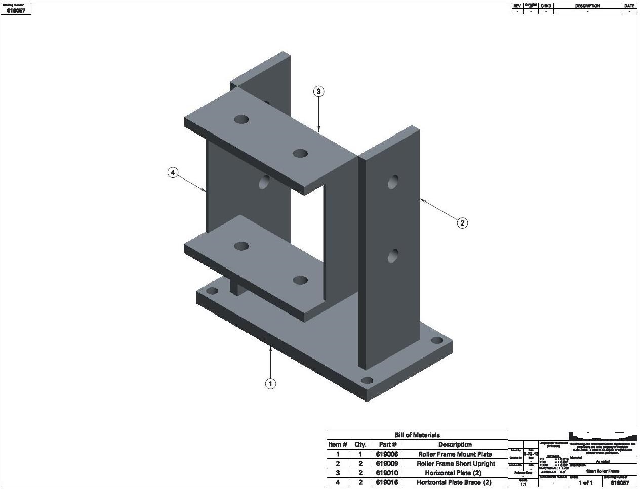
Sep 24, 2013
11:53 AM
- Mark as New
- Bookmark
- Subscribe
- Mute
- Subscribe to RSS Feed
- Permalink
- Notify Moderator
Please log in to access translation
Sep 24, 2013
11:53 AM
Hi Kaci,
when you create pdf with Stroke All Fonts, then your config.pro file must contain:
use_8_plotter_pens yes
pdf_use_pentable YES
pen_table_file c:\ptc\test.pnt !*** this is an example
Put the following lines (see Brent Drysdale answer) in c:\ptc\test.pnt and experiment with the width of pen 2 (if your drawing has ANSI settings) or pen 8 (if your drawing has DIN settings). I suggest to set 0.001 cm as width value.
*************************************************
! This is a pen table file.
! use for PDF creation within ProE WF5 (Creo Elements/Pro) M100. Brent Drysdale 07Aug2012
! Pen 1 = white entities (object lines)
! Pen 2 = yellow entities (text, dimensions, cross hatching)
! Pen 3 = gray entities (hidden lines)
! Pen 4 = red entities (Highlight - Primary (Dark Red)Selected (Red)Secondary Selected (Orange) All items plot as solid lines:
! Spline surface grid (does not plot in drawings)
! Pen 5 = green entities (sheetmetal)
! Pen 6 = cyan entities (section)
! Pen 7 = dark gray entities (dimmed e.g. tangent edges)
! Pen 8 = blue entities (spline surface grid) [use for drawing perimeter border in format]
pen 1 thickness .035 cm; color 0.0 0.0 0.0
pen 2 thickness .018 cm; color 0.0 0.0 0.0
pen 3 thickness .018 cm; color 0.0 0.0 0.0
pen 4 thickness .050 cm; color 0.0 0.0 0.0
pen 5 thickness .035 cm; color 0.0 0.0 0.0
pen 6 thickness .018 cm; color 0.0 0.0 0.0
pen 7 thickness .008 cm; color 0.0 0.0 0.0
pen 8 thickness .050 cm; color 0.0 0.0 0.0
******************************************************
Martin Hanak
Martin Hanák
Sep 24, 2013
12:07 PM
- Mark as New
- Bookmark
- Subscribe
- Mute
- Subscribe to RSS Feed
- Permalink
- Notify Moderator
Please log in to access translation
Sep 24, 2013
12:07 PM
I'm going to suggest you might have some changes from the default assigned text color. This might be taking on the line weight of a different pen like Geometry or something.
Sep 24, 2013
12:32 PM
- Mark as New
- Bookmark
- Subscribe
- Mute
- Subscribe to RSS Feed
- Permalink
- Notify Moderator
Please log in to access translation
Sep 24, 2013
12:32 PM
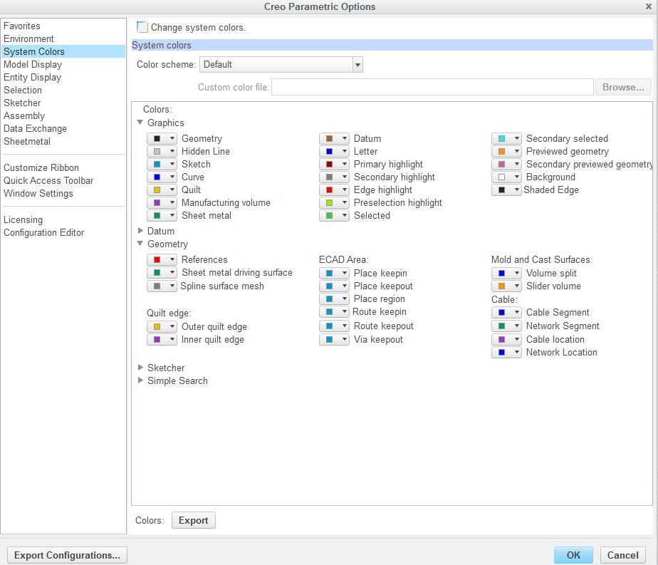
These are my colors:
Sep 24, 2013
12:43 PM
- Mark as New
- Bookmark
- Subscribe
- Mute
- Subscribe to RSS Feed
- Permalink
- Notify Moderator
Please log in to access translation
Sep 24, 2013
12:43 PM
Hi Kaci,
the pentable must work. If you need my further assistance, please upload some example drawing& model.
Martin Hanak
Martin Hanák
Sep 24, 2013
03:56 PM
- Mark as New
- Bookmark
- Subscribe
- Mute
- Subscribe to RSS Feed
- Permalink
- Notify Moderator
Please log in to access translation
Sep 24, 2013
03:56 PM
Hey Kaci,
Could you just test the PDF export with a TTF font that comes with the default instalation of Creo?
These fonts should be in the <installdir>\Creo 2.0\Common Files\M020\text\fonts\.... depending on your subversion number.
~Jakub
Sep 24, 2013
04:17 PM
- Mark as New
- Bookmark
- Subscribe
- Mute
- Subscribe to RSS Feed
- Permalink
- Notify Moderator
Please log in to access translation
Sep 24, 2013
04:17 PM
Right... here is what I am thinking is that the text on your images are black, not blue as the system color chart shows for letters. So what is happening is that somehow the letters were changed to black - geometry color so they are printing heavy like component edges are printed. So when the font is stroked, it is stroked with the geometry pen, not the letter pen.
I could be all wet and there is something else making the letters black, but without analyzing a file, I am only suggesting this as a possibility.
Sep 25, 2013
09:26 AM
- Mark as New
- Bookmark
- Subscribe
- Mute
- Subscribe to RSS Feed
- Permalink
- Notify Moderator
Please log in to access translation
Sep 25, 2013
09:26 AM
Is there anyway I can send you an A size format file and see if you can figure out whats wrong with it?
I'm about to call its quits.
Sep 25, 2013
01:35 PM
- Mark as New
- Bookmark
- Subscribe
- Mute
- Subscribe to RSS Feed
- Permalink
- Notify Moderator
Please log in to access translation
Sep 25, 2013
01:35 PM
You can attach a file to the post if you click on the "Use advanced editor"... or you can send me private message and I will reply an email address.
Mar 05, 2014
11:37 AM
- Mark as New
- Bookmark
- Subscribe
- Mute
- Subscribe to RSS Feed
- Permalink
- Notify Moderator
Please log in to access translation
Mar 05, 2014
11:37 AM
What do I need to change in my config.pro settings in oreder for my object lines not to appear so thick?
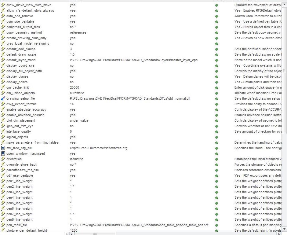
My pentable file: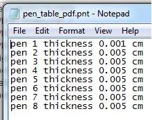
When I finally do print to pdf it says this?? 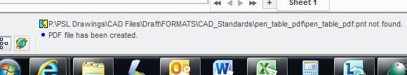
Mar 05, 2014
02:55 PM
- Mark as New
- Bookmark
- Subscribe
- Mute
- Subscribe to RSS Feed
- Permalink
- Notify Moderator
Please log in to access translation
Mar 05, 2014
02:55 PM
Kaci, make sure your pentable file doesn't have a hidden .txt extension.
Next, rename the table to table.pnt and put it in your working folder.
In the export > PDF > options dialog, just check the "Use pentable". This option -only- looks for a table.pnt file in the current working folder. I don't know if a config.pro specified pen table overwrites this or not.
Having said that... remove all references to pentables in your opening config.pro.
The idea is that the system will find the pen table named table.pnt in the working directory if nothing else diverts from this. This is the -best- way to test the table because you know exactly what the system is looking at.
I suggest you try changing all the values to .002 IN for a test. I -know- this works. This should be equivalent to .005 CM. You can compare and see if they are indeed the same in the output.
All geometry by default is assigned one of three pens. Solid geometry lines; hidden lines; and leader lines. Other features are mapped to one of these. So in theory, you should only have to change the 1st 3.
Also, if you are looking at your PDF files with Acrobat Reader, make this change by unchecking this; Edit>Preferences>Page DIsplay:
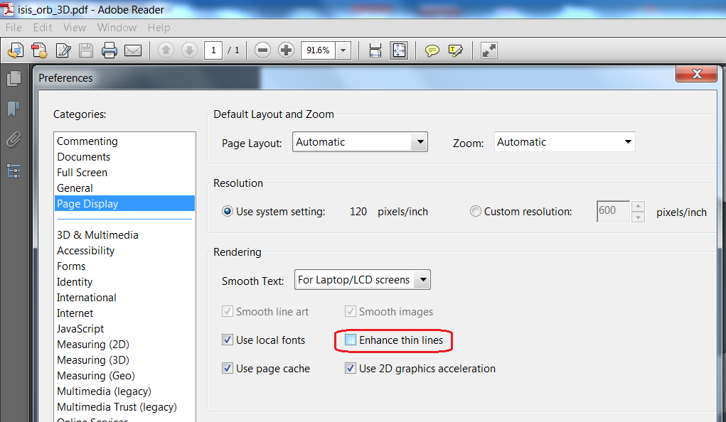
Once you know what to expect, follow through with making the system work reliably using config.pro.
I use this method because I use different pen tables for different clients. Rather than mess with this in config.pro, I just move the right file into the working folder. I also save PDF settings and recall then which also remembers the "Use pentable" option.

Mar 05, 2014
03:09 PM
- Mark as New
- Bookmark
- Subscribe
- Mute
- Subscribe to RSS Feed
- Permalink
- Notify Moderator
Please log in to access translation
Mar 05, 2014
03:09 PM
How do I change the file extension to read .pnt?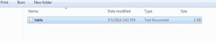
Mar 05, 2014
03:16 PM
- Mark as New
- Bookmark
- Subscribe
- Mute
- Subscribe to RSS Feed
- Permalink
- Notify Moderator
Please log in to access translation
Mar 05, 2014
03:16 PM
In windows 7, in folder; tools>folder options>view
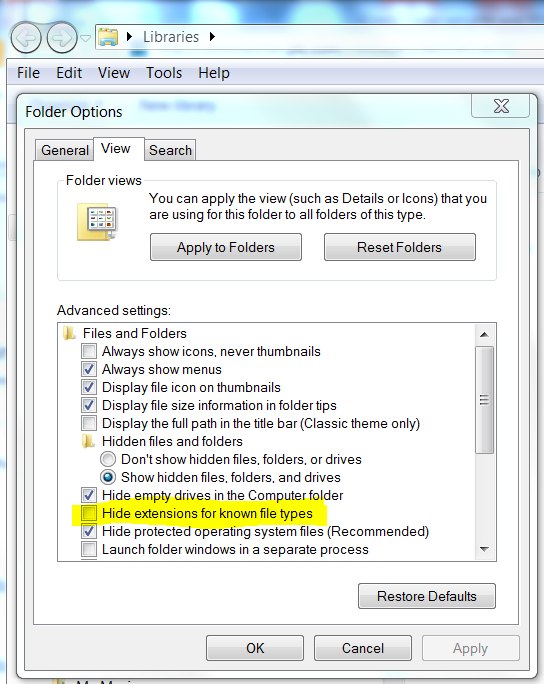
Once you see the extension, you can edit or remove them. I suspect you can change it in the file's properties as well. Just right click the file and select Properties and change it in the General dialog.
Mar 05, 2014
03:59 PM
- Mark as New
- Bookmark
- Subscribe
- Mute
- Subscribe to RSS Feed
- Permalink
- Notify Moderator
Please log in to access translation
Mar 05, 2014
03:59 PM
Ahh, finally it worked!
Thank you!
Mar 05, 2014
05:59 PM
- Mark as New
- Bookmark
- Subscribe
- Mute
- Subscribe to RSS Feed
- Permalink
- Notify Moderator
Please log in to access translation
Mar 05, 2014
05:59 PM
Happy to help!
Nov 24, 2016
09:13 PM
- Mark as New
- Bookmark
- Subscribe
- Mute
- Subscribe to RSS Feed
- Permalink
- Notify Moderator
Please log in to access translation
Nov 24, 2016
09:13 PM
whats font are used in in this attchment
Nov 25, 2016
08:51 AM
- Mark as New
- Bookmark
- Subscribe
- Mute
- Subscribe to RSS Feed
- Permalink
- Notify Moderator
Please log in to access translation
Nov 25, 2016
08:51 AM
Hi,
this discussion was created on 10-May-2013. From my point of view it does not make any sense to add replies to very old discussions.
MH
Martin Hanák
Dec 29, 2015
01:40 PM
- Mark as New
- Bookmark
- Subscribe
- Mute
- Subscribe to RSS Feed
- Permalink
- Notify Moderator
Please log in to access translation
Dec 29, 2015
01:40 PM
hey guys, I have a similar if not same issue, I just want to confirm that before I go changing everything.
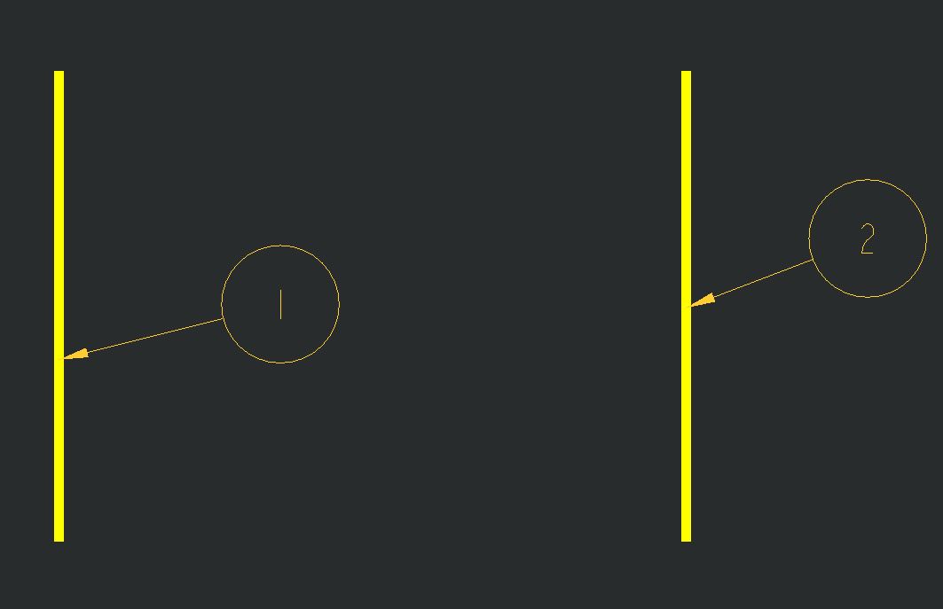
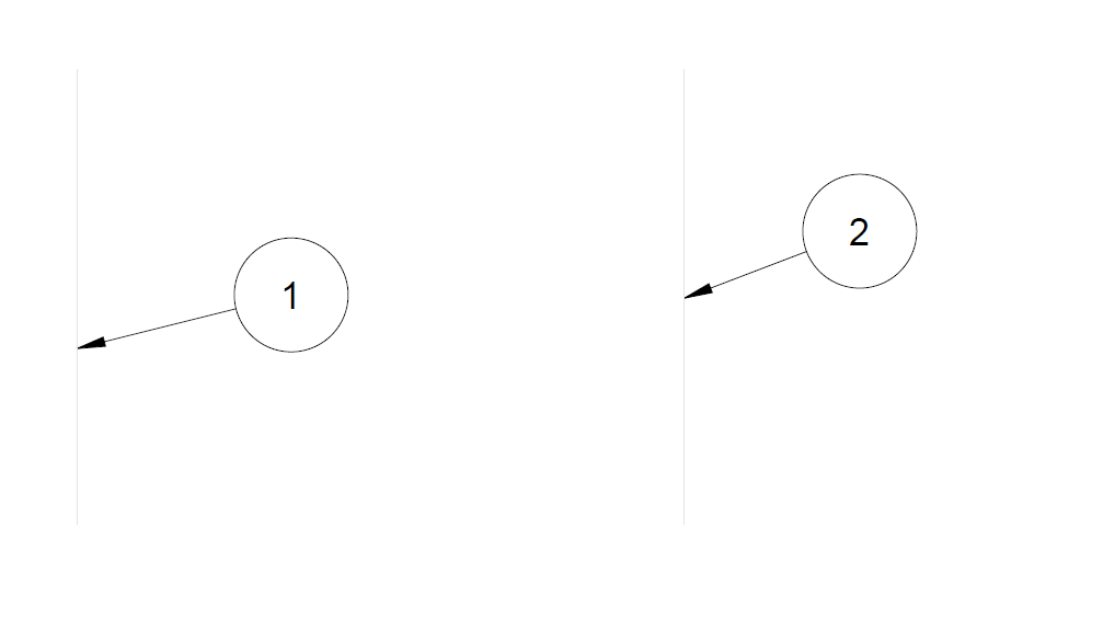
I have a drawing of a dxf file, I change the line style width to 1.000 from 0.000, the line gets wider in the drawing and its what I want but when I print the dxf its really thin just like the rest of the lines.
below is what I want and then what I get after creating a pdf.
thanks in advance
Carlos
Nov 24, 2020
02:55 AM
- Mark as New
- Bookmark
- Subscribe
- Mute
- Subscribe to RSS Feed
- Permalink
- Notify Moderator
Please log in to access translation
Nov 24, 2020
02:55 AM
Hi,
is there any solution for the issue below?
Re: Line weights and PDF files
hey guys, I have a similar if not same issue, I just want to confirm that before I go changing everything.
I have a drawing of a dxf file, I change the line style width to 1.000 from 0.000, the line gets wider in the drawing and its what I want but when I print the dxf its really thin just like the rest of the lines.
below is what I want and then what I get after creating a pdf.
thanks in advance
Carlos


0 Kudos


