Community Tip - Learn all about PTC Community Badges. Engage with PTC and see how many you can earn! X
- Community
- Creo+ and Creo Parametric
- 3D Part & Assembly Design
- Re: axis pattern
- Subscribe to RSS Feed
- Mark Topic as New
- Mark Topic as Read
- Float this Topic for Current User
- Bookmark
- Subscribe
- Mute
- Printer Friendly Page
axis pattern
- Mark as New
- Bookmark
- Subscribe
- Mute
- Subscribe to RSS Feed
- Permalink
- Notify Moderator
axis pattern
Hi,
i am using the pattern tool, using axis to definate it. I would like to know if there is a way to make an axis pattern with two axis : i need a 17.39° x-rotation and a 51.13° y-rotation.
I thought in doing firstly the x rotation pattern and use the result to do de y rotation pattern. But i will have to delete de semi acabate pattern which will delete the second one as it is son o the first one. Am i understandable ?
Thank you,
Léo
Solved! Go to Solution.
Accepted Solutions
- Mark as New
- Bookmark
- Subscribe
- Mute
- Subscribe to RSS Feed
- Permalink
- Notify Moderator
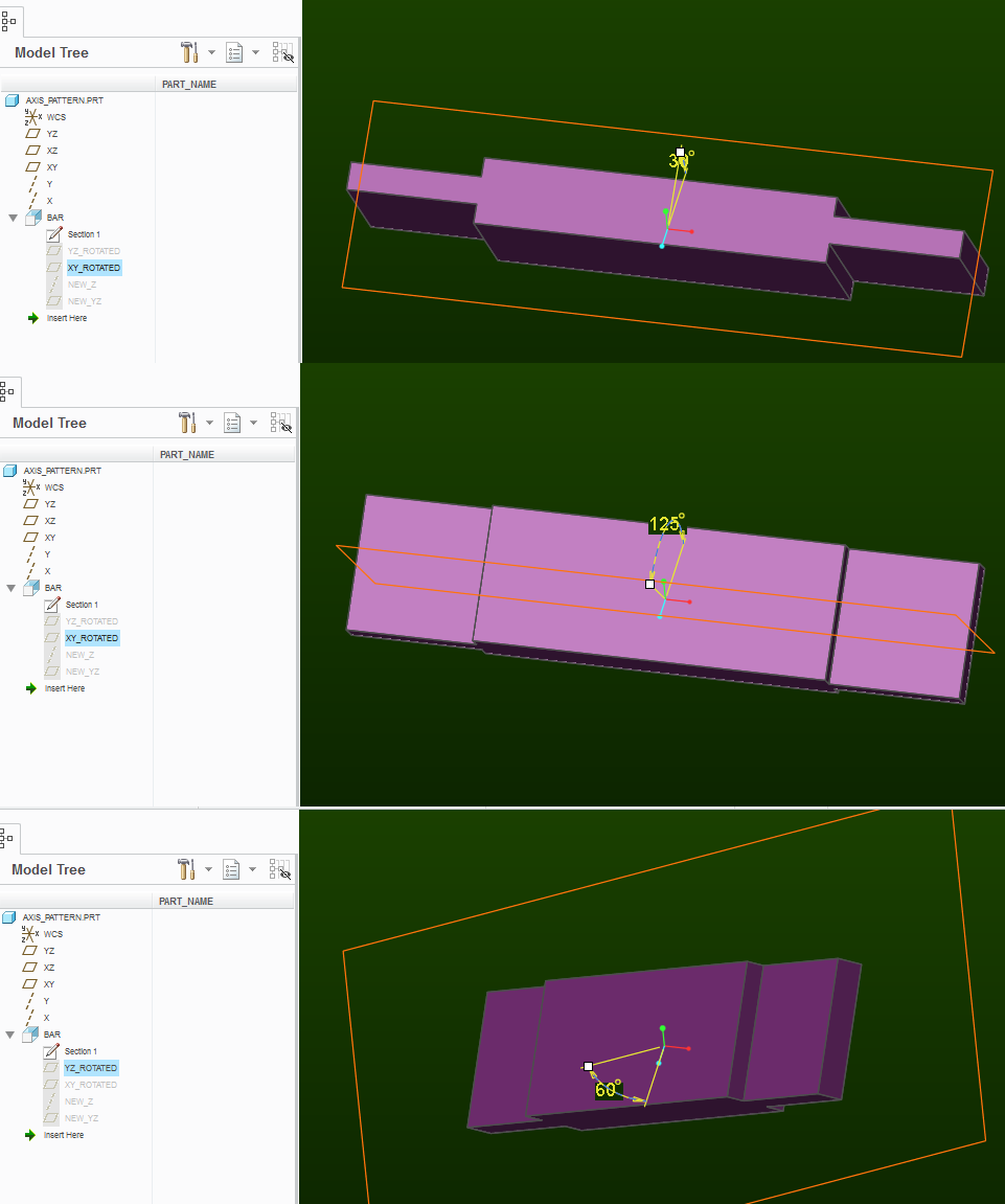
Essentially, the feature "BAR" is made by extruding a sketch made on the plane "XY_ROTATED".
The "XY_ROTATED" plane is defined as going through axis "X" and at an angle to plane "XY".
For your 2nd pattern instance, this angle will be 17degrees.
The plane "YZ_ROTATED" is defined by going through axis "Y" and at an angle to plane "YZ"
The angle of "YZ_ROTATED" plane is the other control angle - in your case 51degrees.
To be able to orient the sketch, I made plane "NEW_YZ" - defined as going through the axis "NEW_Z" and perpendicular to plane "XY_ROTATED".
The axis "NEW_Z" is the intersection of planes "XY_ROTATED" and "YZ_ROTATED".
Notice that if the "XY_ROTATED" plane is at 0 angle, then "NEW_YZ" is coincident with the plane "YZ_ROTATED".
Can you open the file I attached? Then "edit" the two planes to see it in action:
- Mark as New
- Bookmark
- Subscribe
- Mute
- Subscribe to RSS Feed
- Permalink
- Notify Moderator
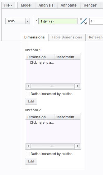
If you have a dimension within the feature for rotation about one of the axes, then, create an axis pattern about the other axis. Within the axis pattern you can click on the dimension tab, click within direction one, select the dimension for rotation about the other axis and type in the increment.
- Mark as New
- Bookmark
- Subscribe
- Mute
- Subscribe to RSS Feed
- Permalink
- Notify Moderator
i tried as you told me dut i have not beem succesful... Could you detail more step by step your explanation ?
In order to better explain my problem my piece is this one 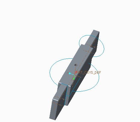
And i need both rotations : 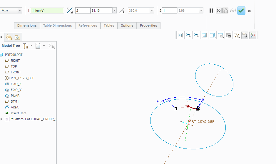
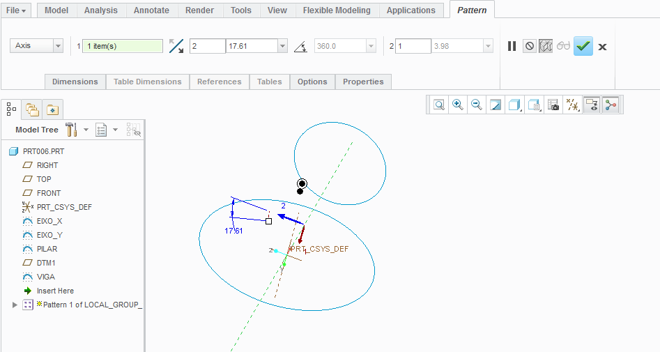
- Mark as New
- Bookmark
- Subscribe
- Mute
- Subscribe to RSS Feed
- Permalink
- Notify Moderator
I'm sorry, I can't understand at all.
Can you sketch a picture?
This is what I guessed you are after:
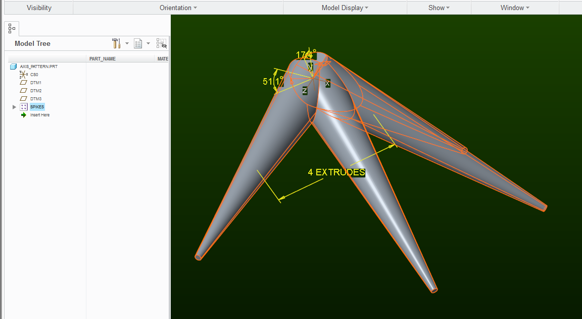
each spike is incrementally re-oriented by simultaneous 17.39° x-rotation and 51.13° y-rotation (about the default coordinate system)
(creo 3.0 example attached)
- Mark as New
- Bookmark
- Subscribe
- Mute
- Subscribe to RSS Feed
- Permalink
- Notify Moderator
The previous pattern behaves funny after about 180 degree mark. This one is better:
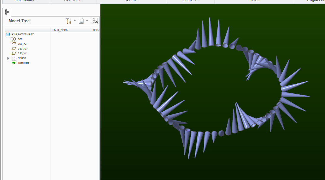
- Mark as New
- Bookmark
- Subscribe
- Mute
- Subscribe to RSS Feed
- Permalink
- Notify Moderator
This is not exactly what i'm searching for.
Look, i did the piece like i want it :
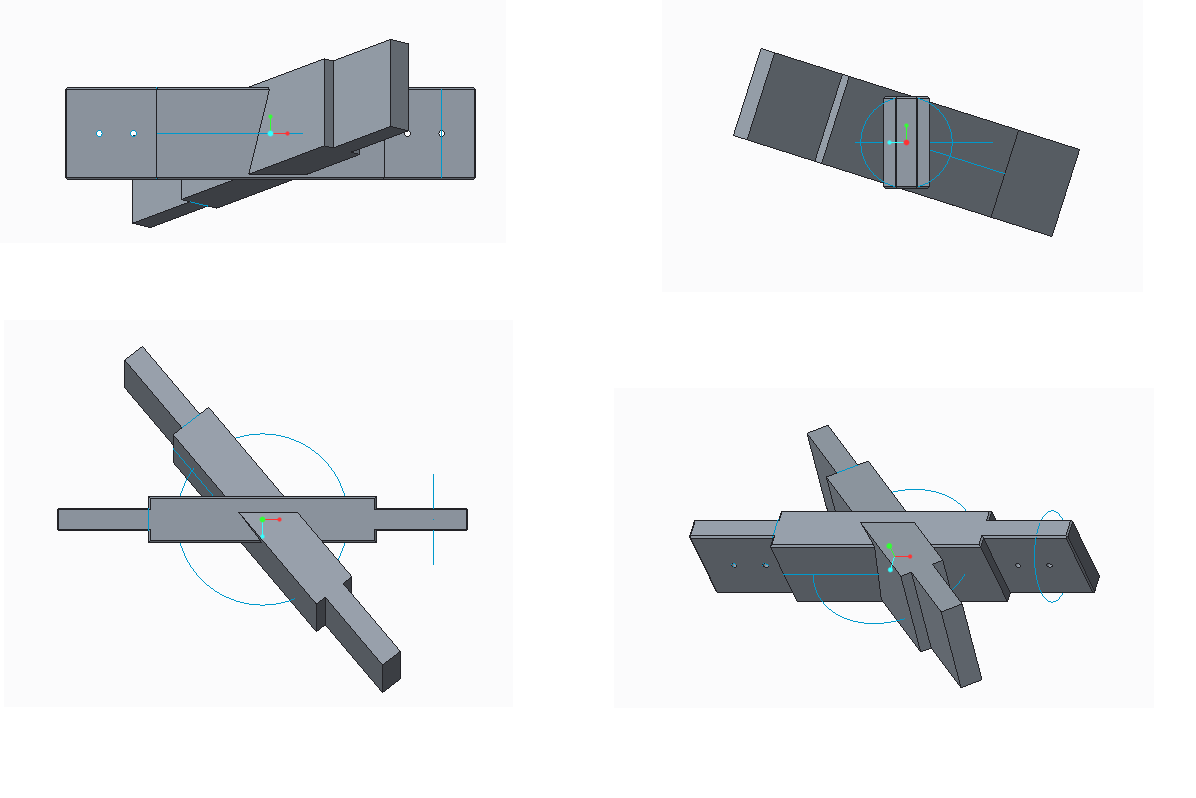
But i did it "manually", i would like to know how to create the second element with the pattern tool. The first element is that one i showed you in my second message.
The second element is like the first one but with a x-rotation and a y-rotation.
thank you for your disponibility,
Léo
- Mark as New
- Bookmark
- Subscribe
- Mute
- Subscribe to RSS Feed
- Permalink
- Notify Moderator
Attached is an example. I setup the sketch plane within the extrude with an angular dimension that could be used within the axis pattern (it starts as 0 degrees).
- Mark as New
- Bookmark
- Subscribe
- Mute
- Subscribe to RSS Feed
- Permalink
- Notify Moderator
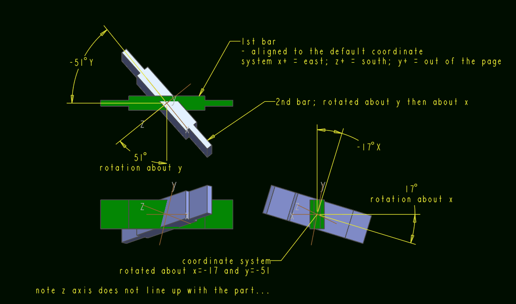
I see. You want the rotation to be about the "global" y axis (green) and then about the "global" x axis (red):
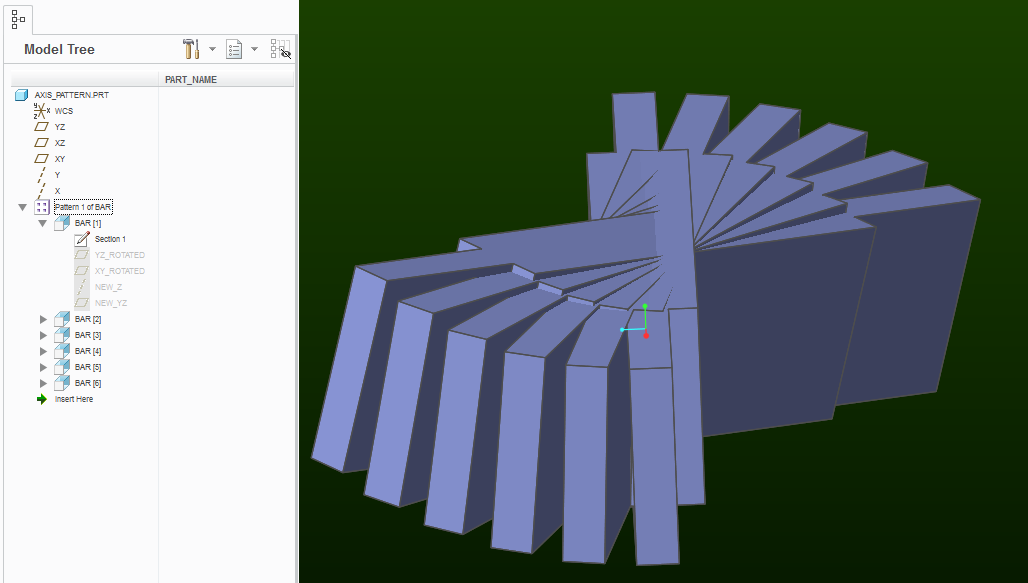
One method is by modeling your geometry such that it is controlled by these two angles. Then during pattern definition, you select "dimension" pattern and then you select both of these dimensions (with the CTRL key) to collect them into the pattern increment definition:
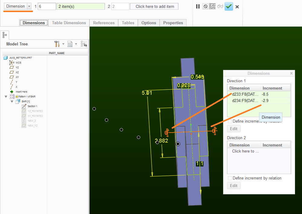
I don't know off the top of my head how to do this with just the "axis" type of pattern.
You can examine the attached file for more clarification.
- Mark as New
- Bookmark
- Subscribe
- Mute
- Subscribe to RSS Feed
- Permalink
- Notify Moderator
Paul Sobejko That's look great ! Can you explain me better how you do the part "modeling your geometry such that it is controlled by these two angles" ?
- Mark as New
- Bookmark
- Subscribe
- Mute
- Subscribe to RSS Feed
- Permalink
- Notify Moderator
Essentially, the feature "BAR" is made by extruding a sketch made on the plane "XY_ROTATED".
The "XY_ROTATED" plane is defined as going through axis "X" and at an angle to plane "XY".
For your 2nd pattern instance, this angle will be 17degrees.
The plane "YZ_ROTATED" is defined by going through axis "Y" and at an angle to plane "YZ"
The angle of "YZ_ROTATED" plane is the other control angle - in your case 51degrees.
To be able to orient the sketch, I made plane "NEW_YZ" - defined as going through the axis "NEW_Z" and perpendicular to plane "XY_ROTATED".
The axis "NEW_Z" is the intersection of planes "XY_ROTATED" and "YZ_ROTATED".
Notice that if the "XY_ROTATED" plane is at 0 angle, then "NEW_YZ" is coincident with the plane "YZ_ROTATED".
Can you open the file I attached? Then "edit" the two planes to see it in action:

- Mark as New
- Bookmark
- Subscribe
- Mute
- Subscribe to RSS Feed
- Permalink
- Notify Moderator
Thank you !!!
- Mark as New
- Bookmark
- Subscribe
- Mute
- Subscribe to RSS Feed
- Permalink
- Notify Moderator
Another way would be to create a offset coordinate system with planes for the geometry and using the rotation angles of the coordinate system.
- Mark as New
- Bookmark
- Subscribe
- Mute
- Subscribe to RSS Feed
- Permalink
- Notify Moderator
Yeah, I tried to used the coordinate system rotation angles, and it wasn't working.
The way the part is shown by the o.p., the rotation is to happen first about the default y (green axis) and then about the default x (red axis).
Took me a while to figure out to figure out that I was not being aware of the order of rotations when offset coordinate system is transformed (first x, then y, then z rotation are applied to generate the new csys):
