
4axis trajectory milling
- Mark as New
- Bookmark
- Subscribe
- Mute
- Subscribe to RSS Feed
- Permalink
- Notify Moderator
4axis trajectory milling
can anyone explain how to do 4axis custom trajectory milling for a simple componenet???..............
This thread is inactive and closed by the PTC Community Management Team. If you would like to provide a reply and re-open this thread, please notify the moderator and reference the thread. You may also use "Start a topic" button to ask a new question. Please be sure to include what version of the PTC product you are using so another community member knowledgeable about your version may be able to assist.
Solved! Go to Solution.
- Labels:
-
General
Accepted Solutions
- Mark as New
- Bookmark
- Subscribe
- Mute
- Subscribe to RSS Feed
- Permalink
- Notify Moderator
Depending on how tight of helix is on you part you are probably going to need to tilt the head. I think you will need a 5 axis tool path for this job. I am sure you know that you need to create a CYS based on how you are fixturing the part. Then you will need to create another CYS that will allow your spindle or table to reposition the part perpendicular to the spindle. When you create you 5 axis toolpath it should do the remaining positioning for you witch should be minor. A 5 axis surface tool path will probably work good, a 5 axis trajectory will work as well but you need to know more about you setup. At any rate I do not know what your machine setup looks like or how you are fixturing the part. But your part needs to be rotating, head needs to be tilting as it moves thru the helix and traversing in the axis you have it fixtured in. You will not be able to machine this part using 4 axis.
- Mark as New
- Bookmark
- Subscribe
- Mute
- Subscribe to RSS Feed
- Permalink
- Notify Moderator
Are you just indexing with a rotary or do you have a full 4 axis cut?
- Mark as New
- Bookmark
- Subscribe
- Mute
- Subscribe to RSS Feed
- Permalink
- Notify Moderator
i want full 4axis cut brother.........
- Mark as New
- Bookmark
- Subscribe
- Mute
- Subscribe to RSS Feed
- Permalink
- Notify Moderator
i am just indexing with rotary bro please help me to get a program for this job
- Mark as New
- Bookmark
- Subscribe
- Mute
- Subscribe to RSS Feed
- Permalink
- Notify Moderator
If you are just indexing you have to create a CYS for each rotation, I would name the CYS the angle you want to cut at. You should also set you retract plane to a cylinder on your operation setup. Whenever you create a toolpath you need to select the CYS you want to cut at and that should get you going.
- Mark as New
- Bookmark
- Subscribe
- Mute
- Subscribe to RSS Feed
- Permalink
- Notify Moderator
Ok sir Is there any options to view job rotation in creo2.0 Thank You for your reply sir...........
- Mark as New
- Bookmark
- Subscribe
- Mute
- Subscribe to RSS Feed
- Permalink
- Notify Moderator
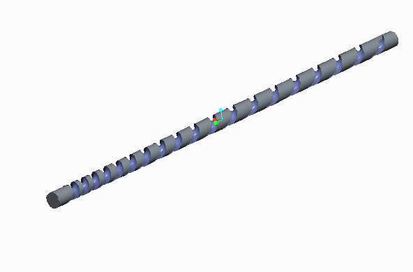
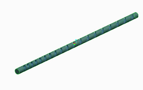
My surface wraps around the part i.e (variable pitch thread in cylindrical job) and we have heidenhain 5axis machine which has 3axis milling head and two axis rotary table (which has rotation about x-axis(4th axis) with a swivel base rotation(5th axis)) and I m going to rotate the x axis through 90deg and to hold the job along y-axis, So the swivel base(5th axis) has to index simultaneously while the tool moves along y-axis so that I can mill this job using this machine. We want circular thread in the job So I m going to use ball milling tool to machine the job. In creo Is there any options to machine such job without 4axis multax machining because in this the milling head is not damped it has an additional rotary axis about y-axis. Please Sir give me your suggestion for this problem........
- Mark as New
- Bookmark
- Subscribe
- Mute
- Subscribe to RSS Feed
- Permalink
- Notify Moderator
Is it possible to post a screen shot of just your stock and setup? You do not have to show the part I know that can be a gray area sometimes. If you can post a screen shot with an arrow pointing at the rotation you would like to cut at that would help. Also if you specify the thread you are trying to cut it sounds like it is a multi start thread maybe.
- Mark as New
- Bookmark
- Subscribe
- Mute
- Subscribe to RSS Feed
- Permalink
- Notify Moderator

- Mark as New
- Bookmark
- Subscribe
- Mute
- Subscribe to RSS Feed
- Permalink
- Notify Moderator
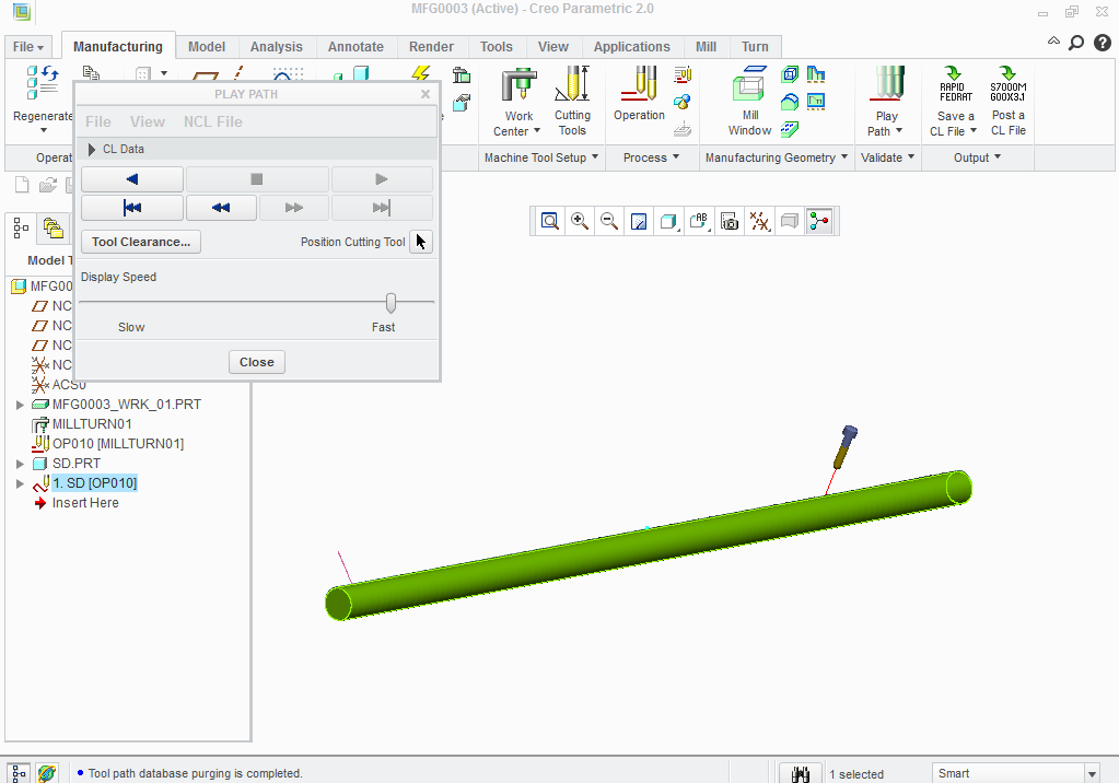
i want the job to index as the tool moves along the axis as mentioned in the image.......pls help me sir can this be done using creo?????
- Mark as New
- Bookmark
- Subscribe
- Mute
- Subscribe to RSS Feed
- Permalink
- Notify Moderator
Yes, CREO can do this what are you getting when you try and creat the trajectory? Is the image attached what you need?

- Mark as New
- Bookmark
- Subscribe
- Mute
- Subscribe to RSS Feed
- Permalink
- Notify Moderator
can you explain me the sequence for 4axis, whenever i try four axis trajectory the tool is parallel to the axis I cant correct it and one more thing is if we use rotation what happens whether tool rotate or job wil rotate???......I want the job to rotate i.e the program should be generated for job indexing position..........
- Mark as New
- Bookmark
- Subscribe
- Mute
- Subscribe to RSS Feed
- Permalink
- Notify Moderator
Depending on how tight of helix is on you part you are probably going to need to tilt the head. I think you will need a 5 axis tool path for this job. I am sure you know that you need to create a CYS based on how you are fixturing the part. Then you will need to create another CYS that will allow your spindle or table to reposition the part perpendicular to the spindle. When you create you 5 axis toolpath it should do the remaining positioning for you witch should be minor. A 5 axis surface tool path will probably work good, a 5 axis trajectory will work as well but you need to know more about you setup. At any rate I do not know what your machine setup looks like or how you are fixturing the part. But your part needs to be rotating, head needs to be tilting as it moves thru the helix and traversing in the axis you have it fixtured in. You will not be able to machine this part using 4 axis.
- Mark as New
- Bookmark
- Subscribe
- Mute
- Subscribe to RSS Feed
- Permalink
- Notify Moderator
k sir thank you for your reply.........
- Mark as New
- Bookmark
- Subscribe
- Mute
- Subscribe to RSS Feed
- Permalink
- Notify Moderator
Matt,
I have a similar case. Machining half the profile of helix in upper portion of cylinder. I need to include tool length compensation but unable to locate the option.
Im looking for TL compensation to convert code from one format to other.
From:
N9X78.4Z41.046
N10X77.391Z41.043
N11X76.211Z40.85A41.984
N12X74.759Z40.834
N13X73.165Z40.805
N14X71.987Z39.857A41.413
N15X71.01Z39.828
N16X70.009Z39.795
To:
X.905 Z.357 A-.713
X1.414 Z.441 A-1.379
X2.598 Z.612 A-2.687
X5.057 Z.964 A-5.316
X7.6 Z1.34 A-7.926
X8.907 Z1.534 A-9.226
X10.239 Z1.729 A-10.521
X11.599 Z1.924 A-11.811
X12.985 Z2.119 A-13.096
X14.4 Z2.313 A-14.377


