
Turn on suggestions
Auto-suggest helps you quickly narrow down your search results by suggesting possible matches as you type.
Showing results for
Please log in to access translation
Turn on suggestions
Auto-suggest helps you quickly narrow down your search results by suggesting possible matches as you type.
Showing results for
Community Tip - Stay updated on what is happening on the PTC Community by subscribing to PTC Community Announcements. X
- Community
- Creo+ and Creo Parametric
- Manufacturing (CAM)
- Chamfer with size related to another edge
Translate the entire conversation x
Please log in to access translation
Options
- Subscribe to RSS Feed
- Mark Topic as New
- Mark Topic as Read
- Float this Topic for Current User
- Bookmark
- Subscribe
- Mute
- Printer Friendly Page
Chamfer with size related to another edge
Sep 01, 2016
09:43 AM
- Mark as New
- Bookmark
- Subscribe
- Mute
- Subscribe to RSS Feed
- Permalink
- Notify Moderator
Please log in to access translation
Sep 01, 2016
09:43 AM
Chamfer with size related to another edge
Hi,
I have two square tubes that need to be welded together with an angle of 90° and with each of them cutted at 45° (as in the picture, hoping it is clear enough):
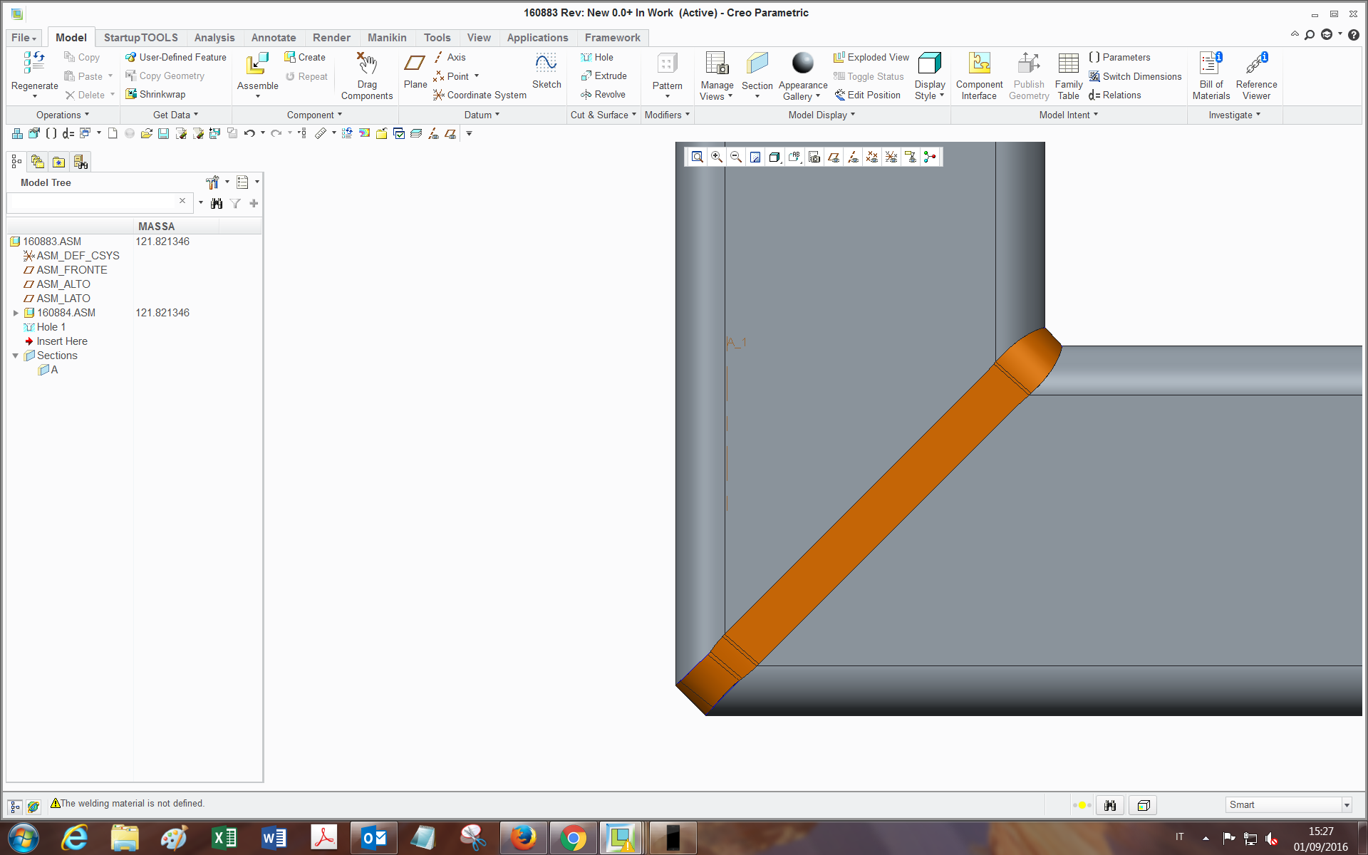
and in order to do a proper and completely filling welding, I need to prepare the edges with a chamfer on the ends of both tubes (like a V-Butt weld indeed).
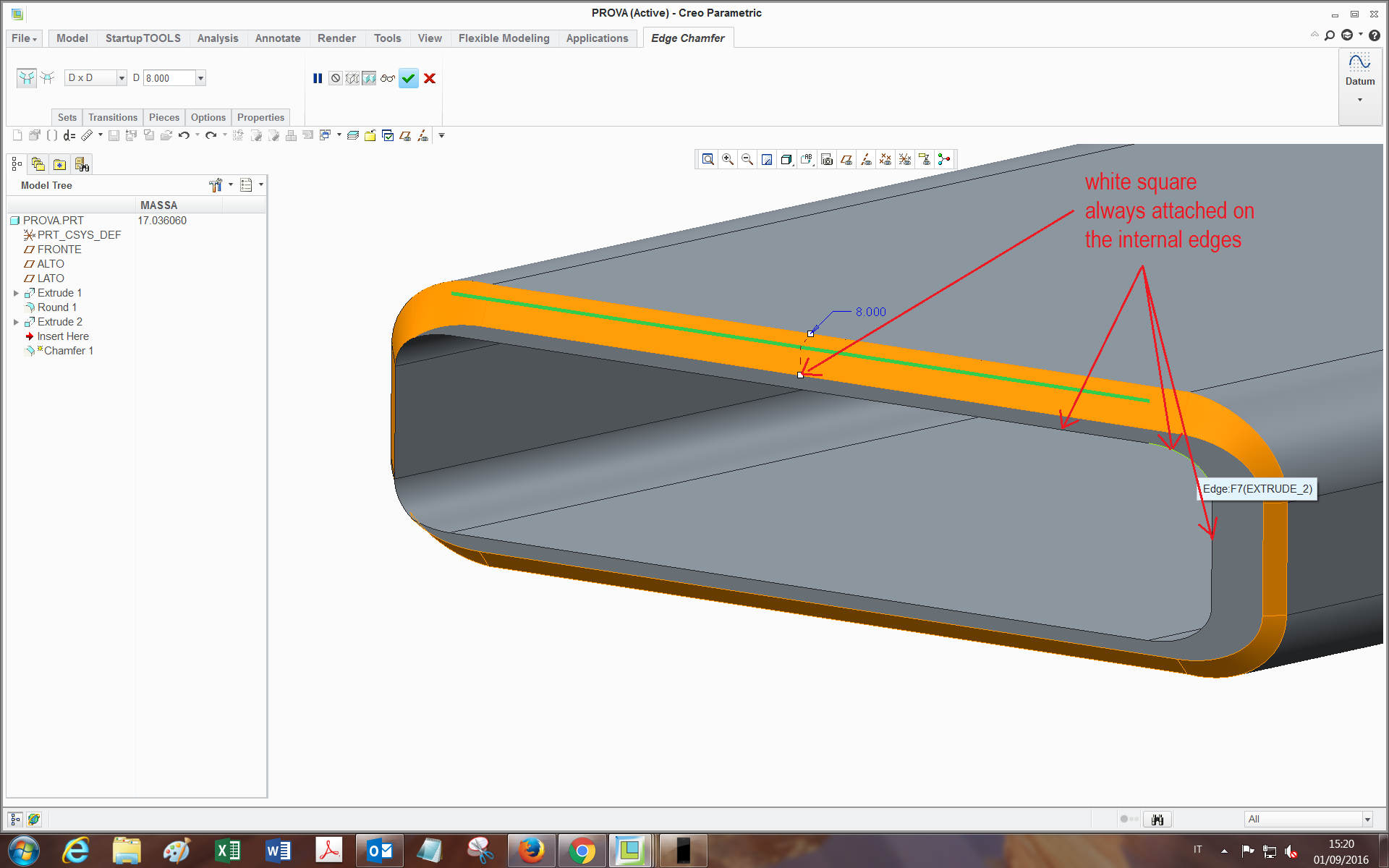
If I just make a chamfer feature on the edge, being it with a constant size, the chamfer doesn't remove material in the same way through the whole edge loop (leaves some flat surfaces, and the reason is related to the geometry).
I am searching for a way to have the white square end of the chamfer being tied everywhere to the inside edge, which would be perfect for my purpose.
I have tried many ways: selecting reference instead of value, by performing a sweep with the two chains and changing the options (normal to trajectory, to surface, etc etc...), but with no success.
Maybe with the sweep is feasible (and I may be missing something). I would like to avoid the edge prep feature of the welding (admitted it can do this), since it has created problems in the past and I also need to have the feature present and editable in the tubes .prt for manufacturing reasons.
Also, I could find a workaround but as far as I am able to, it has too many features and gets heavy in assemblies.
Has someone already achieved this or knows how could I do?
Many thanks,
Bye
This thread is inactive and closed by the PTC Community Management Team. If you would like to provide a reply and re-open this thread, please notify the moderator and reference the thread. You may also use "Start a topic" button to ask a new question. Please be sure to include what version of the PTC product you are using so another community member knowledgeable about your version may be able to assist.
Solved! Go to Solution.
ACCEPTED SOLUTION
Accepted Solutions
Sep 01, 2016
01:48 PM
- Mark as New
- Bookmark
- Subscribe
- Mute
- Subscribe to RSS Feed
- Permalink
- Notify Moderator
Please log in to access translation
Sep 01, 2016
01:48 PM
This one uses Offset and Boundary Blend.
Constant offset at 1T.
Check the boundary blend options in the attached file.
The way the two profiles join is manageable in the control points (piece to piece works well here).
Creo 2.0 commercial version attached.
22 REPLIES 22
Sep 01, 2016
01:24 PM
- Mark as New
- Bookmark
- Subscribe
- Mute
- Subscribe to RSS Feed
- Permalink
- Notify Moderator
Please log in to access translation
Sep 01, 2016
01:24 PM
You might try a sweep rather than a chamfer.
You can also try trimming the outside surface and blending it back with a boundary blend.
Like everything Creo, there are a number of ways to get to a desired result.
One problem is that one side is already at 45 degrees.
The transition is not as straight forward as you would like it to be.
The sweep feature will show you some of the pitfalls.
Sep 01, 2016
01:48 PM
- Mark as New
- Bookmark
- Subscribe
- Mute
- Subscribe to RSS Feed
- Permalink
- Notify Moderator
Please log in to access translation
Sep 01, 2016
01:48 PM
This one uses Offset and Boundary Blend.
Constant offset at 1T.
Check the boundary blend options in the attached file.
The way the two profiles join is manageable in the control points (piece to piece works well here).
Creo 2.0 commercial version attached.
Sep 02, 2016
11:55 AM
- Mark as New
- Bookmark
- Subscribe
- Mute
- Subscribe to RSS Feed
- Permalink
- Notify Moderator
Please log in to access translation
Sep 02, 2016
11:55 AM
Hi Tom,
thank you very much for your replies, indeed it's pretty much what I was hoping for!
I didn't know about some of the options inside the features.
Also, by watching a bit inside I found that:
-The boundary blend turns out less twisted if I select Control points -> Fit: Piece to Piece;
-The solidify can be done also with the remove material option and flipping the direction: at first seems to be digging inside the tube, but after confirmation it's all solid. (Also because I didn't get well the function of the third icon (the one you used)..)
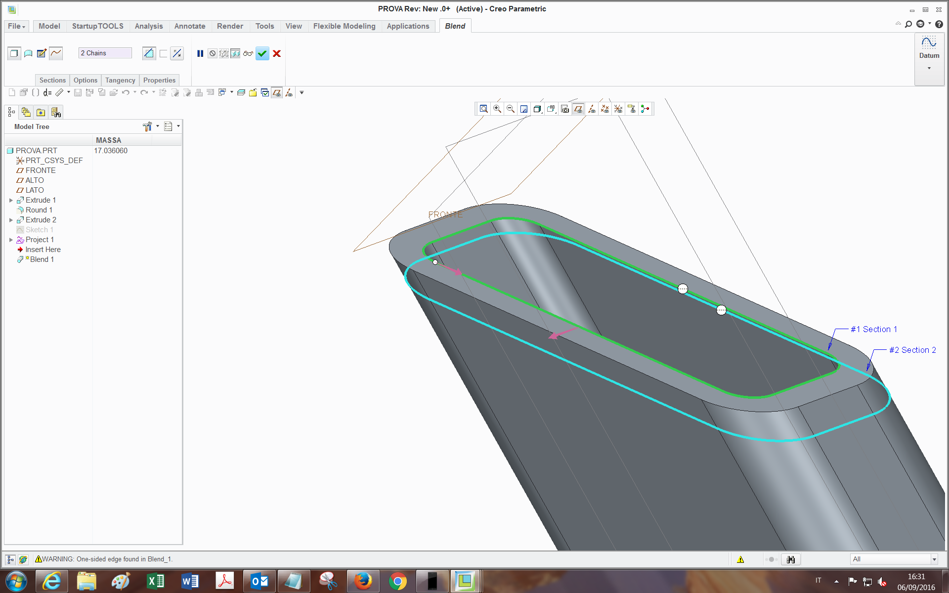
If in the boundary blend I may want to select, as outer chain, isn't the tube inside edge (green in picture):
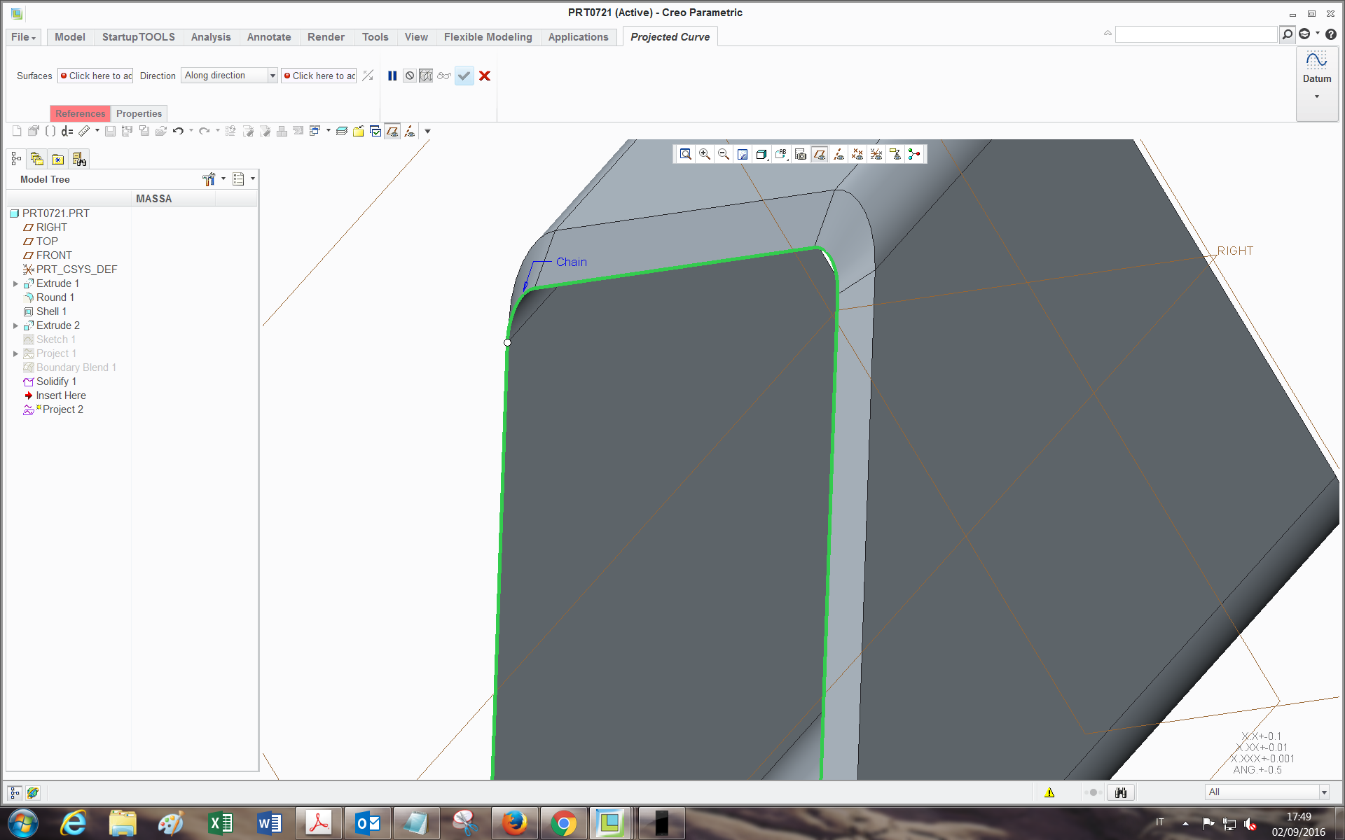
but another chain obtained offseting from this one by (let's say) 1 mm, do you think it's feasible by using project feature?(as far as I tried, didn't work out).
thanks
Bye
Sep 02, 2016
12:35 PM
- Mark as New
- Bookmark
- Subscribe
- Mute
- Subscribe to RSS Feed
- Permalink
- Notify Moderator
Please log in to access translation
Sep 02, 2016
12:35 PM
I used Intersect to scribe the line on the part for the Boundary Blend.
Indeed, however you decide to create that second chain is perfectly acceptable.
Just remember that quite often we do something only to find it didn't do what our mind expected it to do.
When you dig deep into Creo, you will find subtle variations depending on how things are selected.
Just keep in mind that Creo is VERY literal; it does exactly what you tell it to do. No fudging!
Sep 05, 2016
05:53 AM
- Mark as New
- Bookmark
- Subscribe
- Mute
- Subscribe to RSS Feed
- Permalink
- Notify Moderator
Please log in to access translation
Sep 05, 2016
05:53 AM
Hi Antonius,
yes I also noticed that (having dealt with it for enough time  )...(which has also its pros sometimes). I was asking you about the options just to know whether you selected them on purpose and if there was a reason for it or not. For the 1 mm space, I found a way with copy-paste edge->offset.
Thanks
bye
Sep 05, 2016
02:04 PM
- Mark as New
- Bookmark
- Subscribe
- Mute
- Subscribe to RSS Feed
- Permalink
- Notify Moderator
Please log in to access translation
Sep 05, 2016
02:04 PM
Yes, I always check the options in boundary blend. They make a huge difference.
I also tend to add points on the fly for aligning connectivity.
Personally I avoid Copy/Paste features. Don't ask me why because I don't know.
edit: now I see why you are asking. I forgot to save with the "piece to piece" option selection.
Piece to piece works well when you have 2 of the same outlines at different scales.
Also check for rotation when aligning the 2 or more sections.
Sep 06, 2016
10:23 AM
- Mark as New
- Bookmark
- Subscribe
- Mute
- Subscribe to RSS Feed
- Permalink
- Notify Moderator
Please log in to access translation
Sep 06, 2016
10:23 AM
Yes, definitely, in fact sometimes the boundary firstly seems to be unfeasible (doesn't show up in orange), when you just have to turn the white dot and untwist it (like the blend feature).
The fact of the copy->paste, it's indeed the only way I found to overwrite a Curve over an edge with just one feature.
Bye
Sep 02, 2016
01:17 PM
- Mark as New
- Bookmark
- Subscribe
- Mute
- Subscribe to RSS Feed
- Permalink
- Notify Moderator
Please log in to access translation
Sep 02, 2016
01:17 PM
Here's another way:
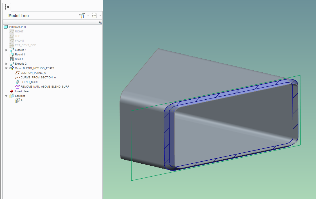
You get "scribe" the chamfer edges by using a curve from cross-section function (generate cross-section using datum plate offset from the mitered surface).
Also, instead of boundary blend, use the basic blend to generate the cutting surface - use "Selected sections" option, and create 2 blend sections - 1st from the curve loop and the 2nd from the edge loop in the existing geometry:
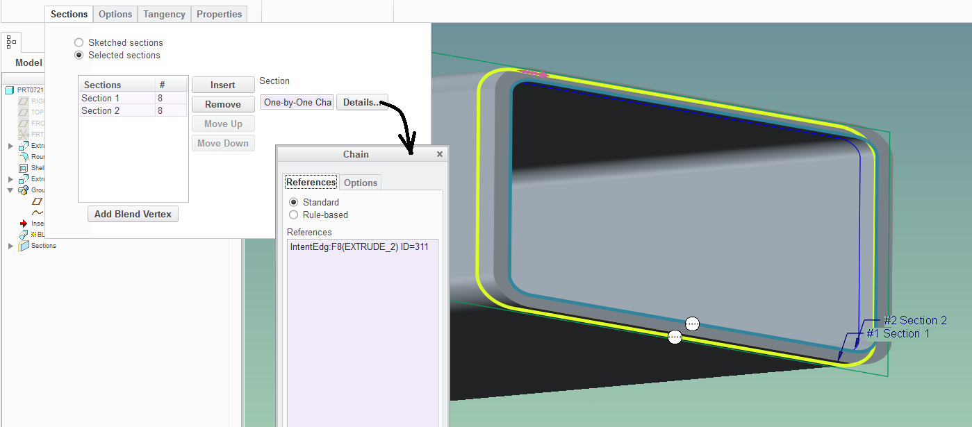
The robustness of the model is improved if you use the rule-based chains and intent edges such as shown above.
Sep 05, 2016
06:09 AM
- Mark as New
- Bookmark
- Subscribe
- Mute
- Subscribe to RSS Feed
- Permalink
- Notify Moderator
Please log in to access translation
Sep 05, 2016
06:09 AM
Hi Paul,
thank you for your solution too. I tried it and managed to perform all the steps except the last one: If I make a blend with the remove material option between the two sections, even with the rule-based option selected (complete loop for both), it just remove a strangely formed volume inside the material:
where am I wrong?
Also, with robustness what do you mean in this case? (less tendency to fail during regeneration?or more robust in view of possible geometry modifications?).
Bye
Sep 05, 2016
02:41 PM
- Mark as New
- Bookmark
- Subscribe
- Mute
- Subscribe to RSS Feed
- Permalink
- Notify Moderator
Please log in to access translation
Sep 05, 2016
02:41 PM
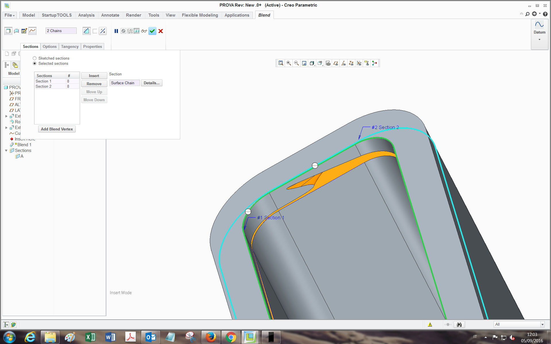
Your two starting points of the sections are not aligned. Either drag the start point to match the other section or create points and join them. Dragging will work in this configuration.
in you model, you have one start point at the upper left round and the other on the upper right at the end of the line.
Sep 06, 2016
10:33 AM
- Mark as New
- Bookmark
- Subscribe
- Mute
- Subscribe to RSS Feed
- Permalink
- Notify Moderator
Please log in to access translation
Sep 06, 2016
10:33 AM
thanks, in fact I had realized it also with the boundary as I was writing to you...it alignes up indeed, but I still can't have it done, by selecting remove material and by flipping the arrow side, it removes the internal part:
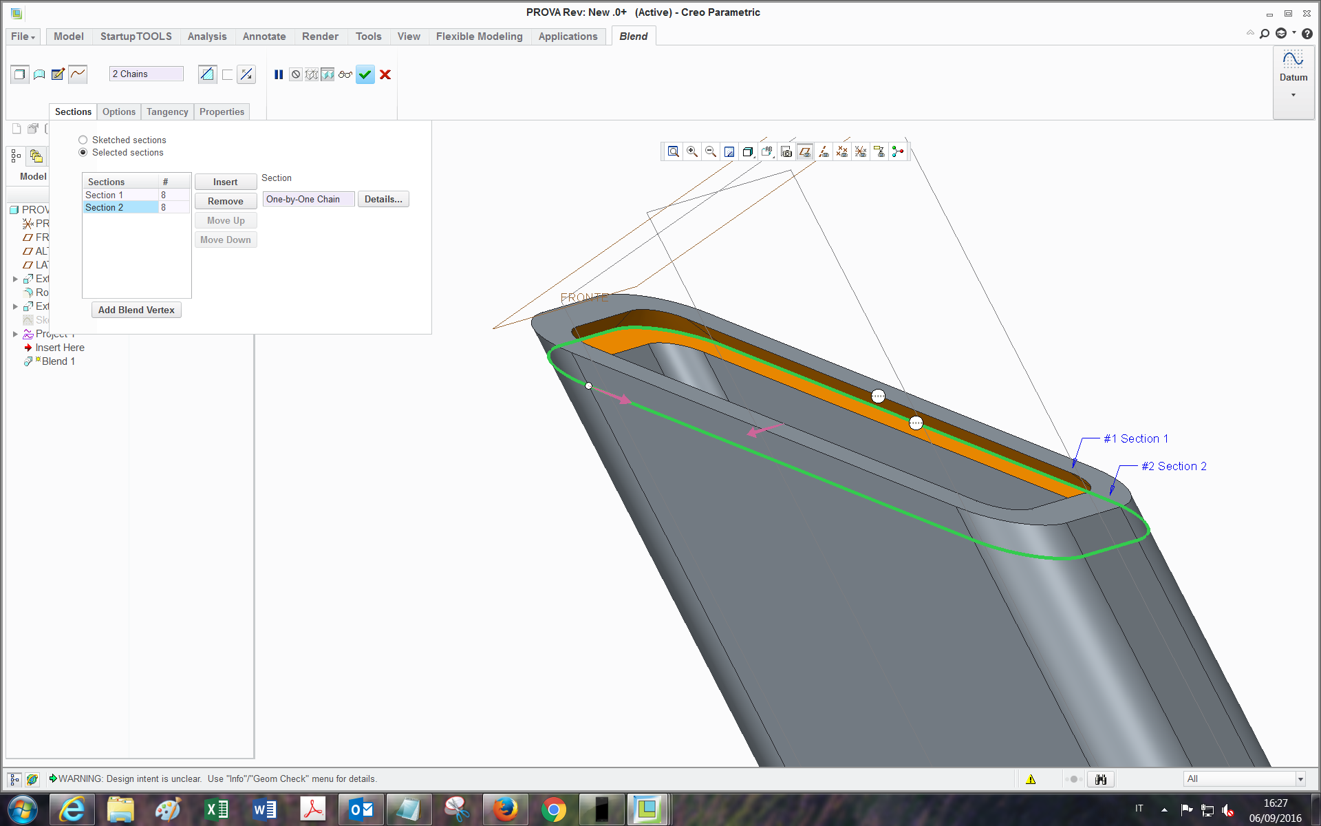
or it does't remove anything and shows an error message after giving the ok:
Sep 06, 2016
11:40 AM
- Mark as New
- Bookmark
- Subscribe
- Mute
- Subscribe to RSS Feed
- Permalink
- Notify Moderator
Please log in to access translation
Sep 06, 2016
11:40 AM
Mine did that too... and then I made it a surface and used solidify and it worked perfectly. Go figure.
Sep 09, 2016
03:23 AM
- Mark as New
- Bookmark
- Subscribe
- Mute
- Subscribe to RSS Feed
- Permalink
- Notify Moderator
Please log in to access translation
Sep 09, 2016
03:23 AM
Ya that works! thanks 
Sep 06, 2016
11:09 AM
- Mark as New
- Bookmark
- Subscribe
- Mute
- Subscribe to RSS Feed
- Permalink
- Notify Moderator
Please log in to access translation
Sep 06, 2016
11:09 AM
Hi Tommaso,
You have to make a blended surface and then use solidify. Like you noticed, the solid remove option doesn't give you the right result in this case.
And you inferred correctly about robustness - when you use the rule based chains, or intent edges, then you have less redefining to do if the geometry changes are made upstream.
Sep 06, 2016
11:46 AM
- Mark as New
- Bookmark
- Subscribe
- Mute
- Subscribe to RSS Feed
- Permalink
- Notify Moderator
Please log in to access translation
Sep 06, 2016
11:46 AM
Paul, on a side-note query: have you ever had your intent chains reverse when making changes?
I use intent curves in making wires where there may be two intersect vectors in the intersect operation.
I select the curves I need and next time I tweak the wire just slightly, the 1st entity is now on the other end of the intent curve.
Sep 06, 2016
12:17 PM
- Mark as New
- Bookmark
- Subscribe
- Mute
- Subscribe to RSS Feed
- Permalink
- Notify Moderator
Please log in to access translation
Sep 06, 2016
12:17 PM
I haven't yet used them for this purpose. Usually I've been building wires / hoses using the curve-thru-points (points defined by offset coordinate system).
I've always been a bit miffed about how difficult is to tweak the shape of your hose because Creo doesn't let you drag the datum points around in an easy fashion.
But maybe using the method of intersecting two planar curves might be the way to go - the editing of the sketches seems much more dynamic. (hmm... dynamic editing only works in part mode - whereas it would be really useful in assembly mode).
Sep 06, 2016
12:59 PM
- Mark as New
- Bookmark
- Subscribe
- Mute
- Subscribe to RSS Feed
- Permalink
- Notify Moderator
Please log in to access translation
Sep 06, 2016
12:59 PM
My use-case was managing a fiber optics bundle.
Managing minimum bend radii and offsets were simple intersecting sketches.
It worked great other than the reversing intent curves.
We'll leave this for a different discussion but if you go there and decide to report this bug, let me know.
Sep 09, 2016
03:26 AM
- Mark as New
- Bookmark
- Subscribe
- Mute
- Subscribe to RSS Feed
- Permalink
- Notify Moderator
Please log in to access translation
Sep 09, 2016
03:26 AM
Ja in fact I noticed that. And will take into account the robustness aspect as they are very critical for other features too.
Sep 06, 2016
12:03 PM
- Mark as New
- Bookmark
- Subscribe
- Mute
- Subscribe to RSS Feed
- Permalink
- Notify Moderator
Please log in to access translation
Sep 06, 2016
12:03 PM
This version is done using variable-section sweep - advantage: just one feature:
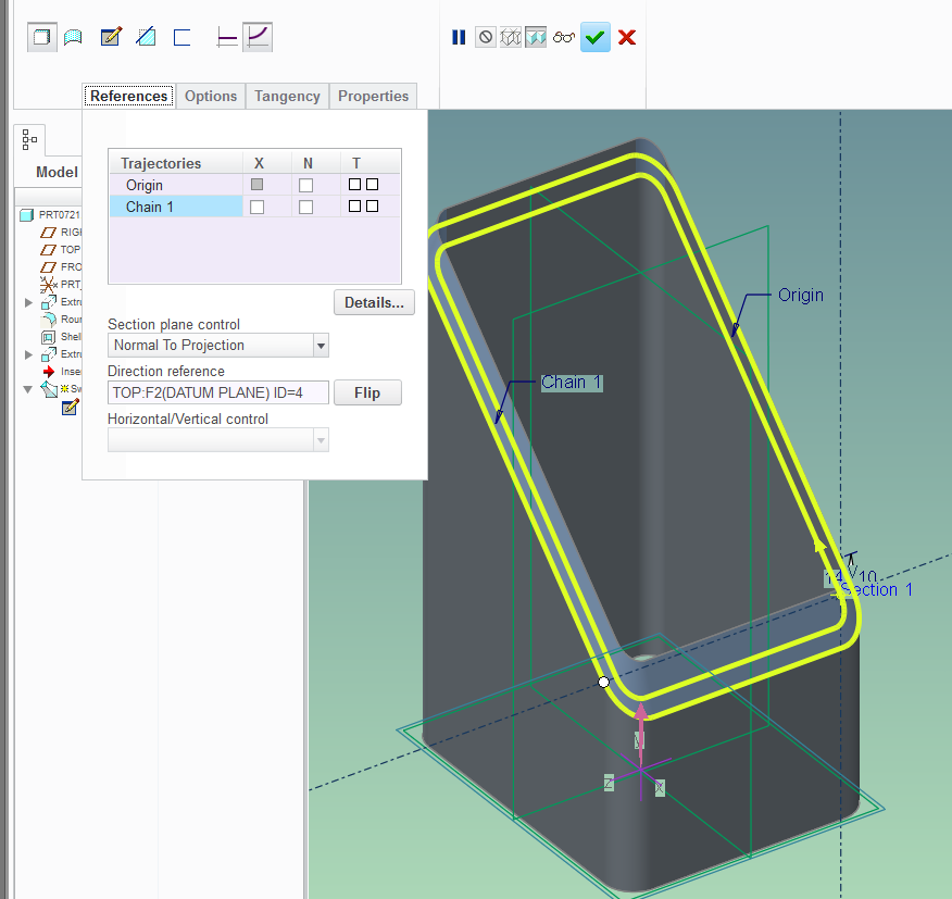
(Creo 2.0 model attached)
Sep 09, 2016
04:20 AM
- Mark as New
- Bookmark
- Subscribe
- Mute
- Subscribe to RSS Feed
- Permalink
- Notify Moderator
Please log in to access translation
Sep 09, 2016
04:20 AM
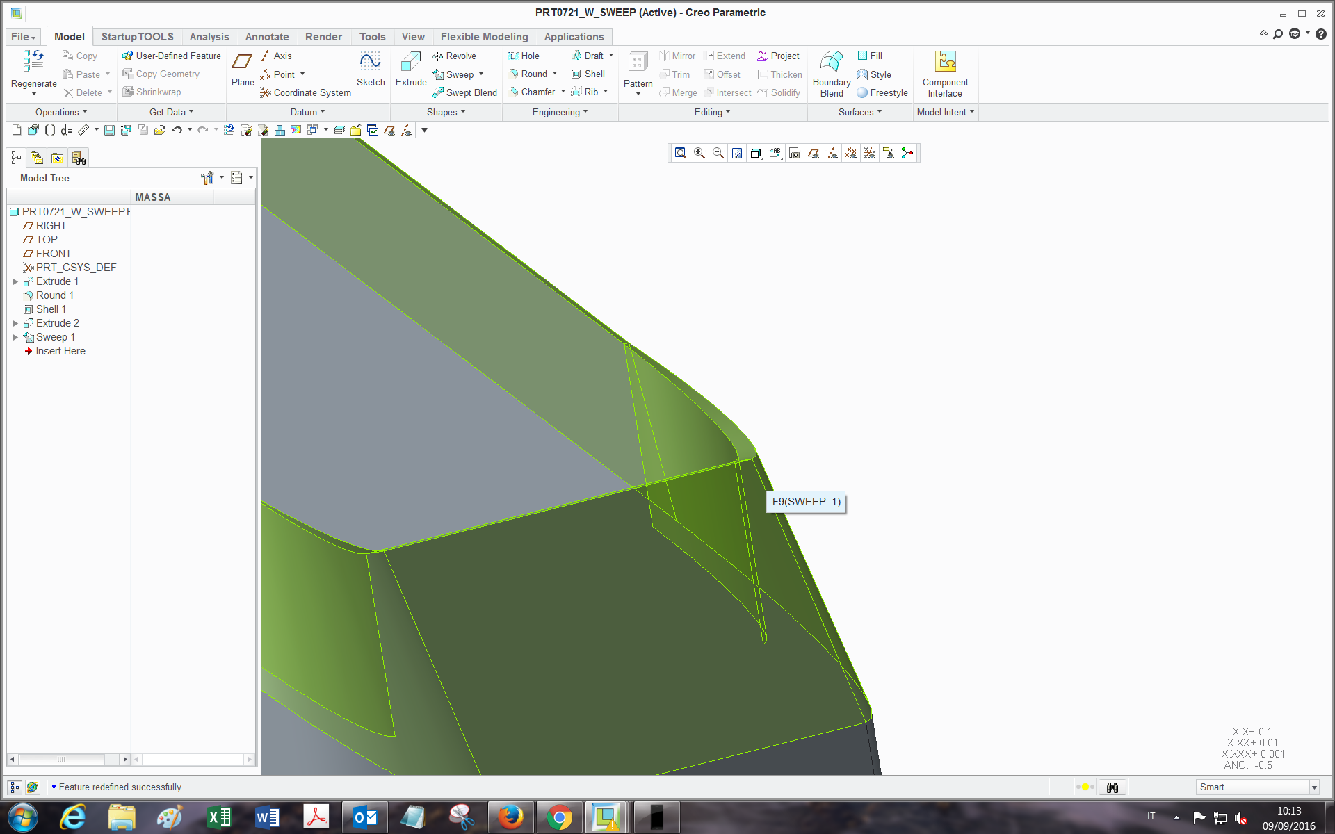
good alternative, hadn't thought it was properly feasible with sweep...in fact I saw you selected "normal to projection"->TOP plane.
The only limit is that If one wants to leave a plane area for beams contact before welding, the area doesn't come out as plane everywhere around the loop:
Sep 09, 2016
10:59 AM
- Mark as New
- Bookmark
- Subscribe
- Mute
- Subscribe to RSS Feed
- Permalink
- Notify Moderator
Please log in to access translation
Sep 09, 2016
10:59 AM
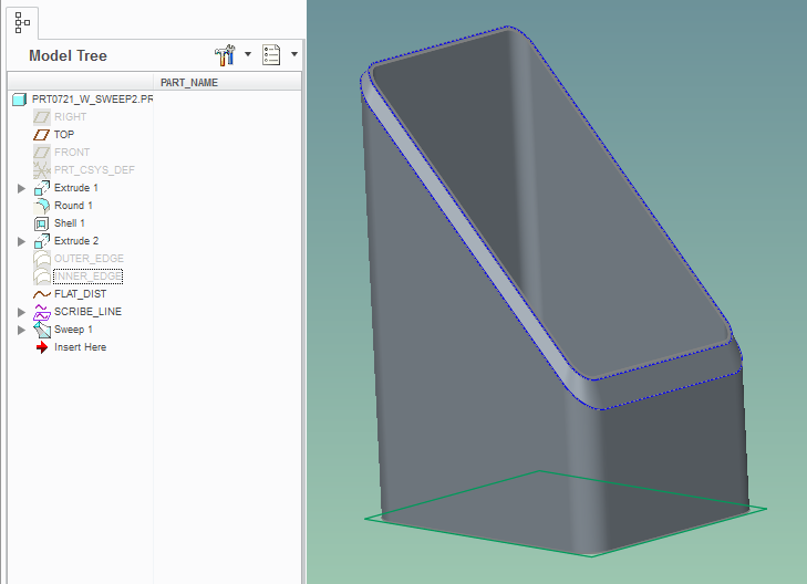
Well, there's a way to do it, though it takes more features:
Sep 13, 2016
06:25 AM
- Mark as New
- Bookmark
- Subscribe
- Mute
- Subscribe to RSS Feed
- Permalink
- Notify Moderator
Please log in to access translation
Sep 13, 2016
06:25 AM
Hi Paul,
yes this works fine too, thanks!
So indeed it can be done with the sweep too..
Bye
Announcements


Top Tags
