1-Visitor
January 19, 2013
Question

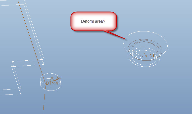
Deform area on a Thread forming punch in sheetmetal

  • January 19, 2013
  • 4 replies
  • 11979 views

Hi folks,

I can't say that I'm the most proficient at using the "deform area" tool, so maybe this is easy.

Can anybody get the Deform Area functionality to work for this thing?


Is it more common to create a datum point and note for the location and name of the tool for this feature when sending to manufacturing?


TYIA,


Josh


deform_area.jpg


This thread is inactive and closed by the PTC Community Management Team. If you would like to provide a reply and re-open this thread, please notify the moderator and reference the thread. You may also use "Start a topic" button to ask a new question. Please be sure to include what version of the PTC product you are using so another community member knowledgeable about your version may be able to assist.

4 replies

17-Peridot
January 19, 2013

This one got me too. Seems difficult to thin the material in Sheetmetal for the pierce and extrude. I ended up making the part outside of Sheetmetal. I'm sure there is a way, but every feature wanted to maintain the material thickness. Since this is not the case with the pierce (it thins as it extrudes), it mattered to me.

Personally, I model that I see. So when I place these kinds of features, I also want to see them. It is too easy to overlook this at a higher level design review and suddenly you find yourself with an interference in the real parts.

Some tips with regard to this in Sheetmetal would be helpful indeed.

13-Aquamarine
January 21, 2013

I actually do not think you can have anything in sheet metal that deviates frrom the standard material thickness unless it's in an area where there's relief. I cannot think of a single instance where I was able to use sheet metal mode to simulate the kind of deformity Joshua is trying to do here. I've always modeled this in regular Pro/E (or Creo).

For example... if I'm designing something that's vacu-formed and I need to show thinning accurately, I take it outside of sheetmetal. Or... if I decide to stay in sheetmetal mode, I add something to the drawing to let the manufacturing vendor know that thinning is acceptable in certain areas. Then I add local notes to point to the areas where thinning is expected/permitted.

JoshH1-VisitorAuthor
1-Visitor
January 21, 2013

Hmmm, guess I'll try to replace this feature with a regular Pro/E formed feature and see if I can get anywhere close. This is geometry that has been translated from another tool. I'm not sure if there was a flat pattern for it before, but I'm pretty sure we'll have to have it in the future.

I know at the TC's, we have discussed with PTC about introducing manufacturing features that produce variable thickness (deep drawing, plastic deformation, etc.), but the technology just wasn't readily available.

Thanks for the feedback Antonius and Brian. It's good to have some validation.

17-Peridot
January 21, 2013

I had run into a model once that might be of interest. There is a way to "compress" an assembly into a part model. I will see if I can post more on this. I do not know if this will work with a sheetmetal model but if I recall correctly, that is where it was used.

Let me get back to you on this. This capability interests me very much as well.

17-Peridot
January 21, 2013

I found the reference and yes, it is done in sheetmetal.

Have look in the help (and knowledgebase, if you have it) on External Inheritance

From the help files:

External Inheritance Features

An external Inheritance feature allows one-way associative propagation of geometry and feature data from a reference part to a target part without the need for assembly context. External Inheritance features are useful when representing the evolution of a design during manufacturing or when creating standard design elements.

You can use external Inheritance features to either add or subtract material from the reference part geometry to or from a target part. Define the location of geometry propagated from the reference part by selecting coordinate systems on the reference and target parts.

A target part can contain one or more external Inheritance features. Features propagated from the reference part are represented in the target part as subfeatures of the external Inheritance feature. You can create a reference pattern in the target part based on the pattern of external Inheritance subfeatures.

Dimensions propagated from the reference part are fully accessible in Assembly, Part, and Detailed Drawings. These dimensions can be shown in a drawing of the target part.

Varied items and external Inheritance feature capabilities are identical to standard Inheritance features.

I have not used this yet but as said, I am very interested in how well this works for this type of scenario. I am not certain I am free to share the file where I found this, so my apologies for not providing that.

17-Peridot
January 22, 2013

Today I had a great opportunity to see how this could best be done. Indeed, there are some -serious- limitations to making features part of the base material in Sheetmetal.

1st I tried the Inheritance Features. I could not get anything to merge with the base sheetmetal part. So I thought, "great, I can make Sheetmetal PEMS and use the as Inheritance features..." NOT. Make a pierce and extrude sheetmetal part and "merge"... NOT The ladder could be inherited but you could not join it to the main model.

So I have never used Form features, until today. Mind you, I am using Creo 2.0 and I have done some sheetmetal model types with good success.

I looked at Joshua's linked model and the 1st thing I noticed is that it doesn't have the "1st wall" feature. This is key to beginning any sheetmetal model. Second, What am I missing here... I cannot see any history in release M030(?) (tools/investigate/model history; we've discussed this before). Lastly, I cannot see any features as they are created from Pattern 9 (unpattern\ungroup) only when the Solidify is applied to I see anything.

So on one of my Creo 2.0 sheetmetal parts I use the "half shear" tutorial to help me learn about form features. I successfully make it work and find I can easily make the feature represented in the initial post. So I do that; reduce the OD if the extruded wall (made with the form feature); add fillet radii to the inside base and the outside thread hole; next apply a cosmetic thread. I do all this in an "unbend" state. I reactivate the Bend Back and the feature moves with the wall as expected.

So a form feature seems to do what you want. You can do more operations to that form feature that are more core feature operations. If you have a lot of these to do, you'll find that they do not pattern, necessarily.

The moral of the story, always generate a "1st wall" feature be it planer or revolve. And create this after the initial datum features.

17-Peridot
January 22, 2013

I have added a Creo 2.0 model of a sheetmetal base with pierce and extrude 4-40 threads replacing PEMs installed at a next level.

Feel free to review it if you can open it. Again, I learned quite a few new things about sheetmetal (do's and don'ts) like what patterns correctly and what doesn't (reference patterns). As with all versions of Pro/E, the cosmetic threads don't follow folds and unfolds unless they are in the 1st wall. You have to play with the layers to have the form tool datums turn off (you cannot select them to hide). You will see what patterned successfully and what failed in the attached file.

Form_feature_pierce-n-extrude.JPG

Patriot_1776
22-Sapphire II
January 29, 2013

I had an issue where a guy had tried to do something in sheetmetal and it almost worked, but I couldn't modify it at ALL. Like Brian said, once you pick a thickness you're done. I think sheetmetal should be an optional package, with the commands inside regular Pro/E, so if you did some sheetmetal part, and then machined some other area, or if you wanted something like sheetmetal (because you needed both folded and flat patterns) but it would in fact be an IM plast part (with bosses, which is impossible in sheetmetal). For me, since I needed a flat state, a state where just the leads were bent, and when the leads and the flex circuit was bent, I ended up having to do my part as a family table assembly of family table parts that all had spinal bend features in it to get what I needed. Something so simple ends up being so difficult......62-8768_I_10MM_FLX_BNT_LED-BODY.JPG