Community Tip - Did you know you can set a signature that will be added to all your posts? Set it here! X
- Community
- Creo+ and Creo Parametric
- Manufacturing (CAM)
- Re: How to revolve a 3D edge ?
- Subscribe to RSS Feed
- Mark Topic as New
- Mark Topic as Read
- Float this Topic for Current User
- Bookmark
- Subscribe
- Mute
- Printer Friendly Page
How to revolve a 3D edge ?
- Mark as New
- Bookmark
- Subscribe
- Mute
- Subscribe to RSS Feed
- Permalink
- Notify Moderator
How to revolve a 3D edge ?
Hello,
I and my colleagues have to design turning and milling tools, thus we often need to check the shape generated by these tools during machining.
As the cutting edges are sometimes not contained in a plane and/or not in a plane containing the axis of revolution of the tool, we cannot simply use the Revolve feature.
The easiest way we found is (in WF5) :
1. Copy/Paste a cutting edge
2. Copy the copied edge
3. Paste special with Rotate transformation (10°) around the tool's axis of revolution
4. Pattern it every 10°
5. Make a boundary blend of all these copied edges
The question is: IS THERE A SINGLE PRO/E FEATURE ABLE TO REVOLVE A 3D EDGE (not contained in a plane) AROUND AN AXIS ?
Thank you. ![]()
This thread is inactive and closed by the PTC Community Management Team. If you would like to provide a reply and re-open this thread, please notify the moderator and reference the thread. You may also use "Start a topic" button to ask a new question. Please be sure to include what version of the PTC product you are using so another community member knowledgeable about your version may be able to assist.
Solved! Go to Solution.
Accepted Solutions
- Mark as New
- Bookmark
- Subscribe
- Mute
- Subscribe to RSS Feed
- Permalink
- Notify Moderator
Edthewrist is right.
Make sure you select only one boundary chain (circle) and one inner chain (your 3D curve) while creating the surface.
~Jakub
- Mark as New
- Bookmark
- Subscribe
- Mute
- Subscribe to RSS Feed
- Permalink
- Notify Moderator
I've run into this before. I feel your pain. I can, for instance, model a 3D trajectory to be machined by a ball end mil, but the resultant geometry does not equal the modeled geometry. This is a known issue for which I know of no easy solution.
- Mark as New
- Bookmark
- Subscribe
- Mute
- Subscribe to RSS Feed
- Permalink
- Notify Moderator
Thank you for your interest Frank.
Our case is a litte bit easier than yours: we just need to visualize the shape generated by the cutting edges with the tools in a steady state, with no feed, but rotating.
A colleague of mine sometimes exports his mills to Unigraphics in order to generate this revolved geometry and then re-imports it in Pro/E... ![]()
But I also missed the "milling" feature during designing special tools.
- Mark as New
- Bookmark
- Subscribe
- Mute
- Subscribe to RSS Feed
- Permalink
- Notify Moderator
Why not use a revolved surface or cut then?
- Mark as New
- Bookmark
- Subscribe
- Mute
- Subscribe to RSS Feed
- Permalink
- Notify Moderator
Because the revolve feature needs a section and an axis of revolution contained in the sketching plane, and in my case the edge is not contained in a plane and/or this plane does not contain the axis of revolution.
Here is a simple example of what I need to do (machining a chamfer with an SNMM insert).
Have a look at the cutting edge's orientation.
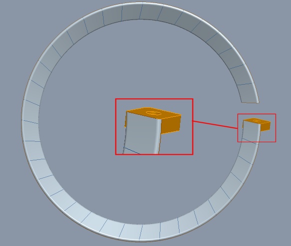
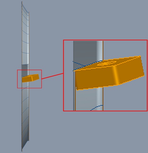
It is quite harder with this kind of mill:
- Mark as New
- Bookmark
- Subscribe
- Mute
- Subscribe to RSS Feed
- Permalink
- Notify Moderator
You can do this using style feature. (You need an ISDX license)
- Mark as New
- Bookmark
- Subscribe
- Mute
- Subscribe to RSS Feed
- Permalink
- Notify Moderator
Could you explain me how to do it? ![]()
I am in the styling menu but I can not figure out how to make a revolved surface...
Thank you ![]()
- Mark as New
- Bookmark
- Subscribe
- Mute
- Subscribe to RSS Feed
- Permalink
- Notify Moderator
Edthewrist is right.
Make sure you select only one boundary chain (circle) and one inner chain (your 3D curve) while creating the surface.
~Jakub
- Mark as New
- Bookmark
- Subscribe
- Mute
- Subscribe to RSS Feed
- Permalink
- Notify Moderator
Thank you.
It is not as straight-forward as I expected it to be but it works fine ! ![]()
- Mark as New
- Bookmark
- Subscribe
- Mute
- Subscribe to RSS Feed
- Permalink
- Notify Moderator
Try to use variable section sweep! It will work. First you have your 3d curve:
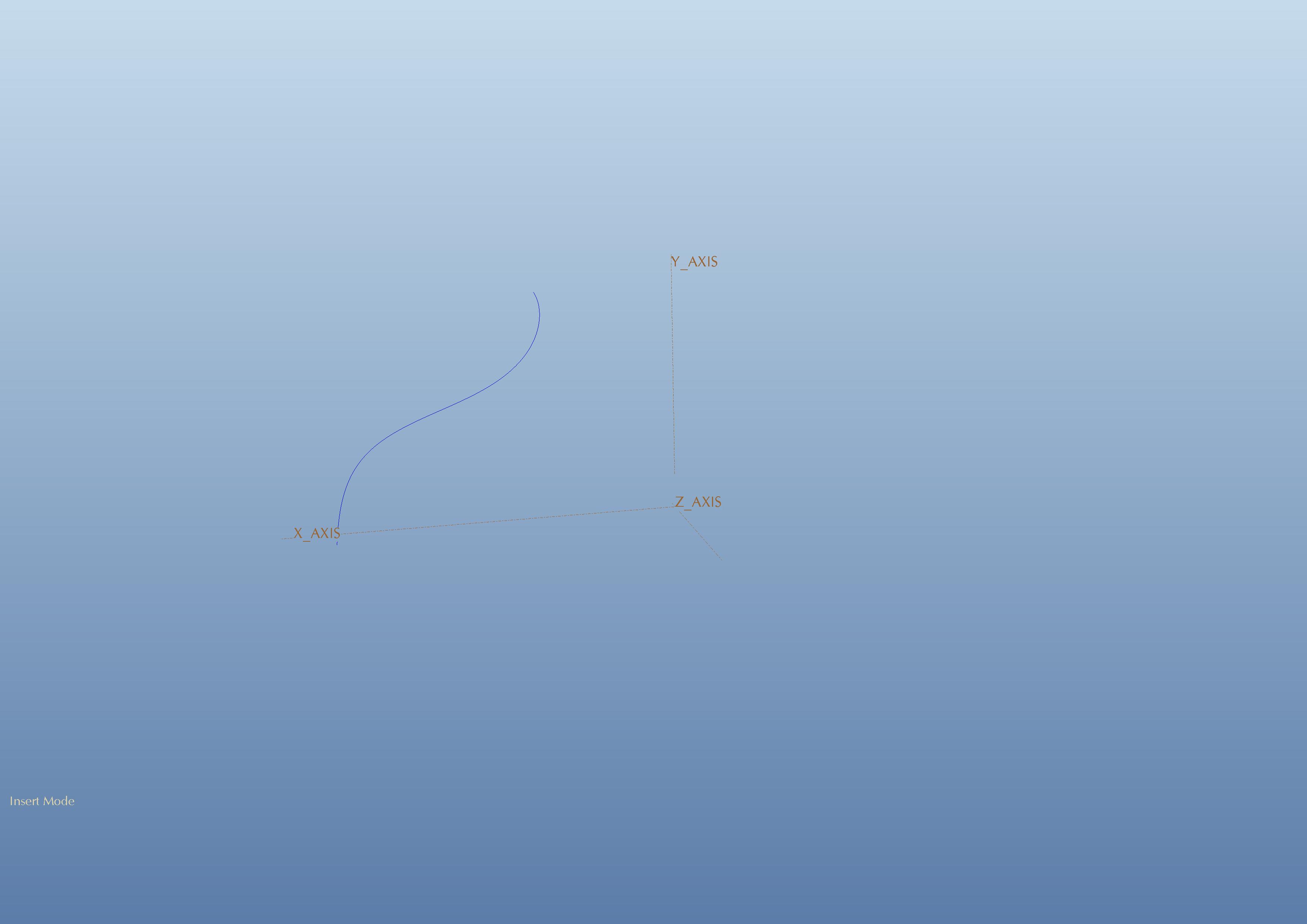
You will need to create a curve instead of centerline of rotation and you will use it as first curve and then yo will pick your 3 d curve as second one.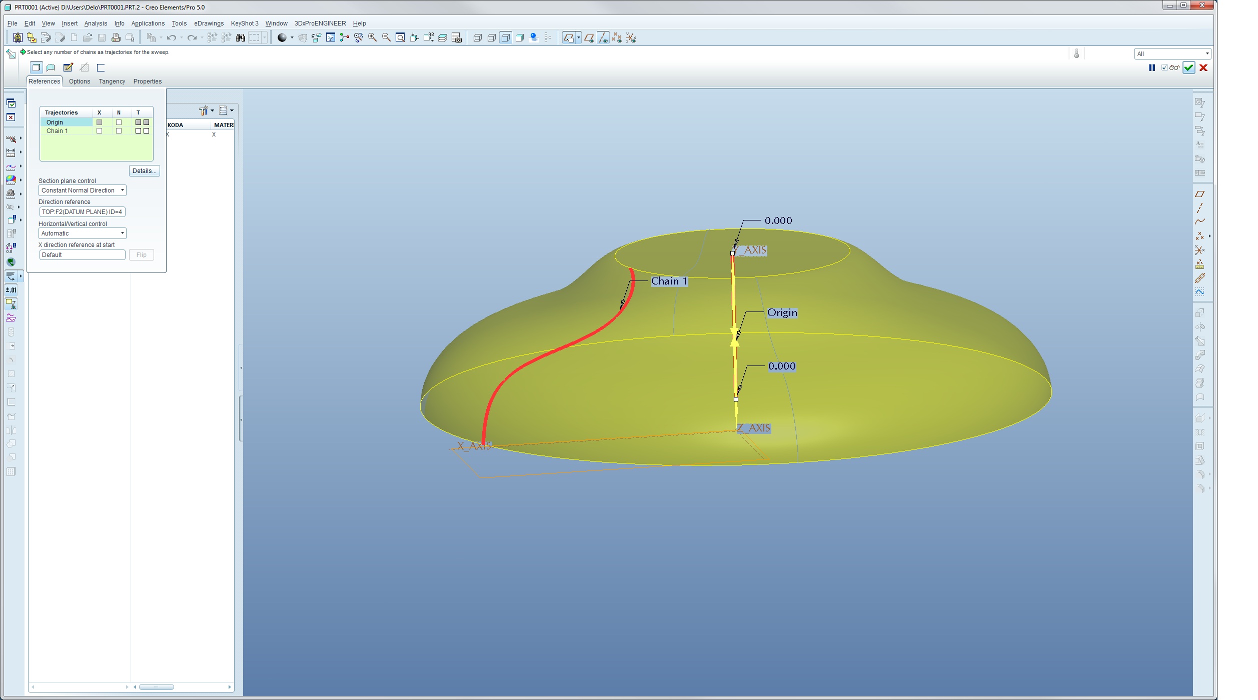
Then go to sketch and create sketched circle with center on first curve and diameter will be driven by your 3 d curve.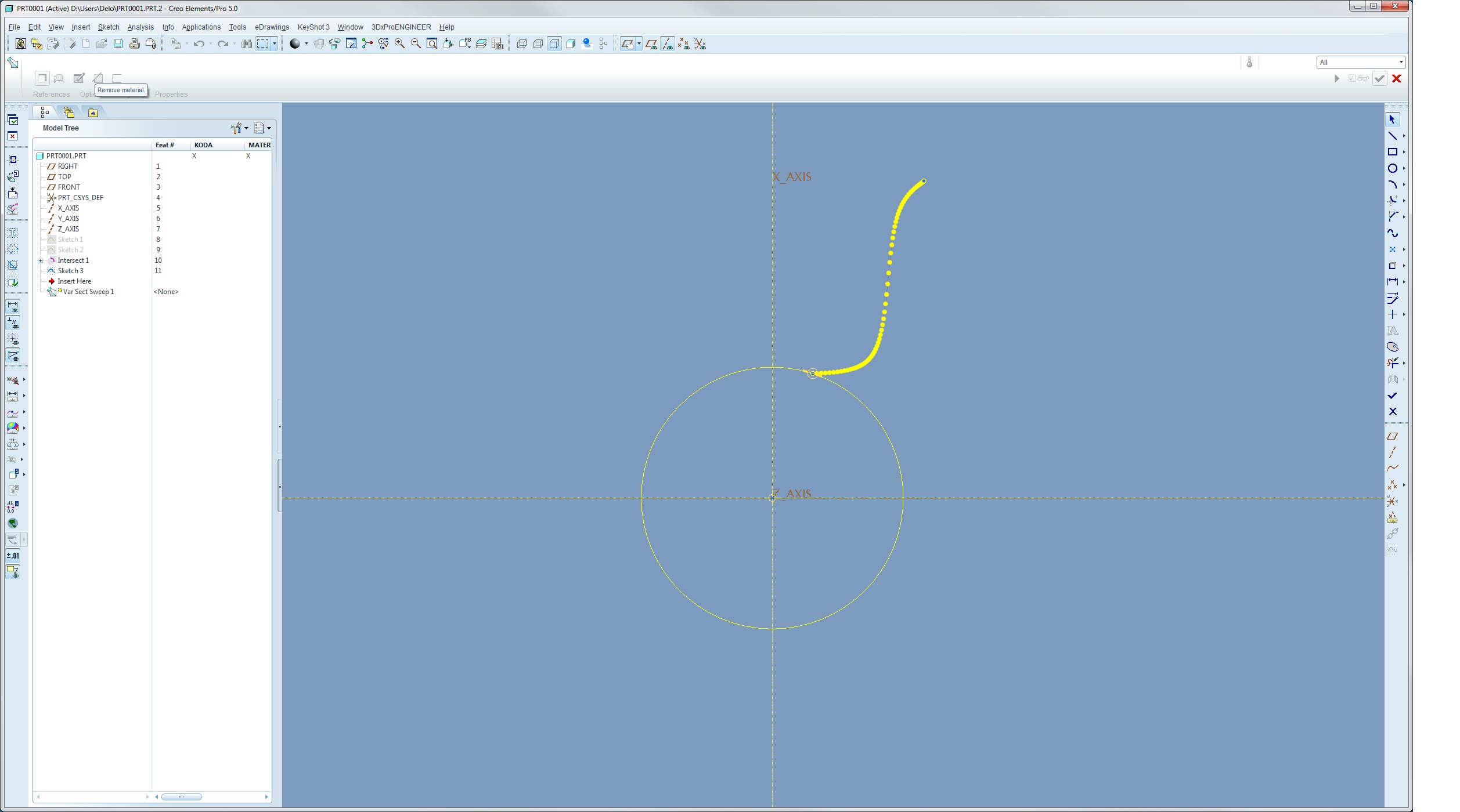
In this way you can create surfaces or solids. Sometime you will need to use constant normal direction for plane control.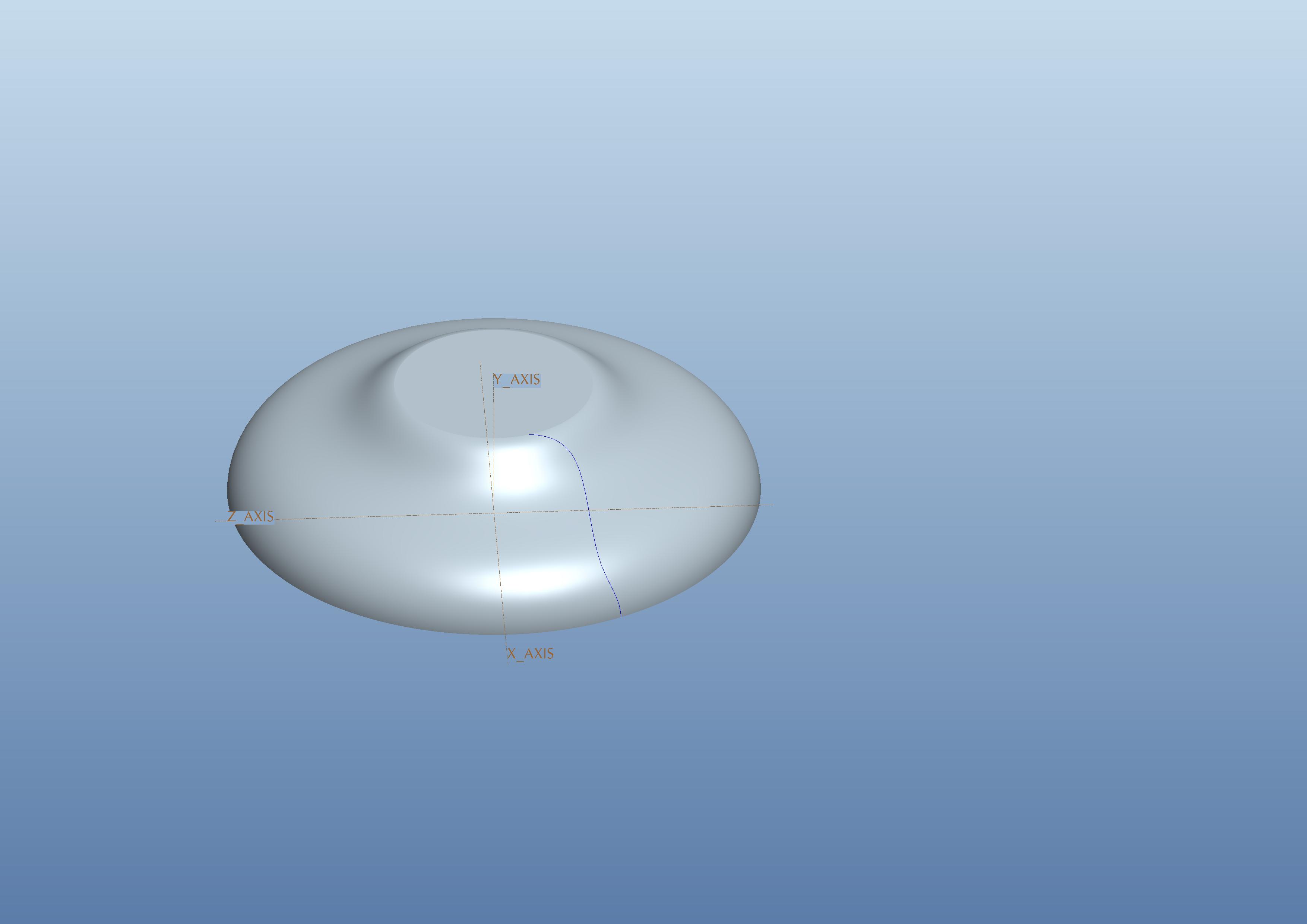
Variable section sweep is rely powerful tool.
If you have any further questions please ask!
Best regards Klemen
- Mark as New
- Bookmark
- Subscribe
- Mute
- Subscribe to RSS Feed
- Permalink
- Notify Moderator
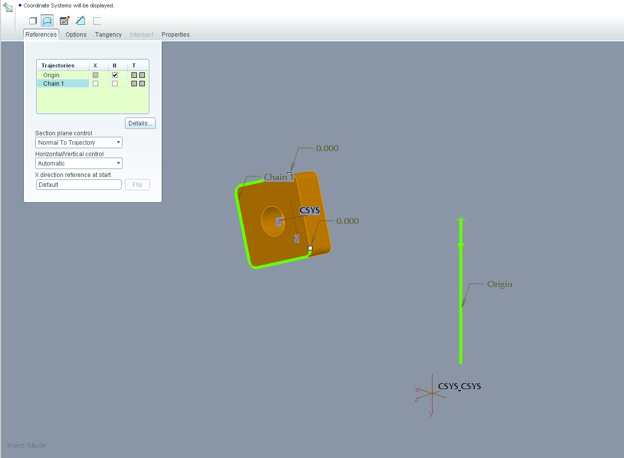
I tried it, but in this case it does not seem to work (the chain has multiple points at the same "level"):
- Mark as New
- Bookmark
- Subscribe
- Mute
- Subscribe to RSS Feed
- Permalink
- Notify Moderator
Can you send me 3d model, please! I will see why is not working!
- Mark as New
- Bookmark
- Subscribe
- Mute
- Subscribe to RSS Feed
- Permalink
- Notify Moderator
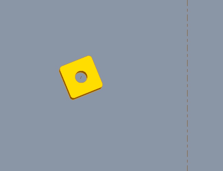
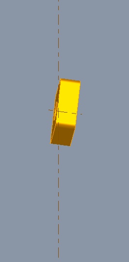
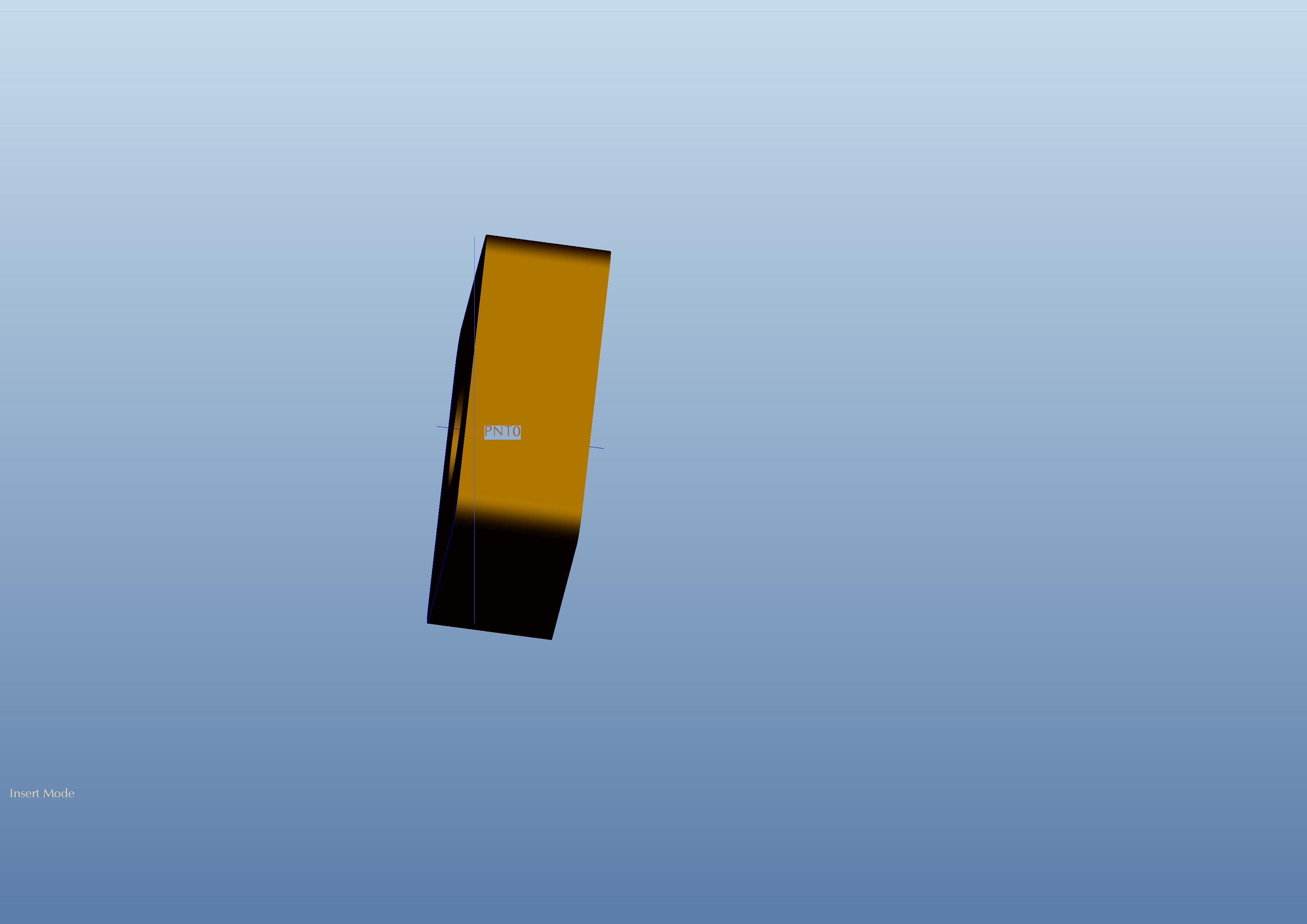
I cannot, but here are a front view and a right view of the cutting insert I used:
- Mark as New
- Bookmark
- Subscribe
- Mute
- Subscribe to RSS Feed
- Permalink
- Notify Moderator
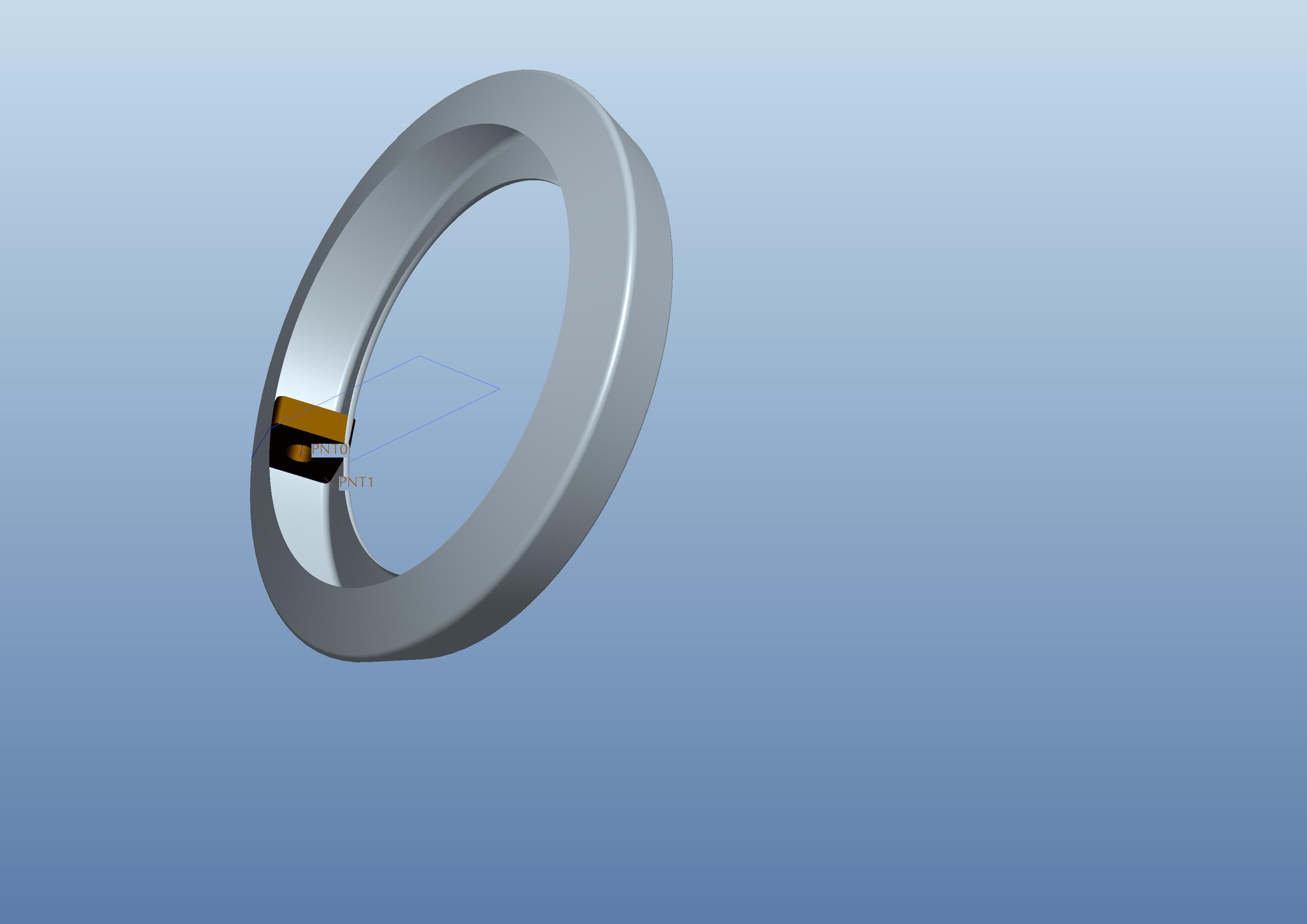
Try to replicate your situation, and it worked, just split it into two surfaces.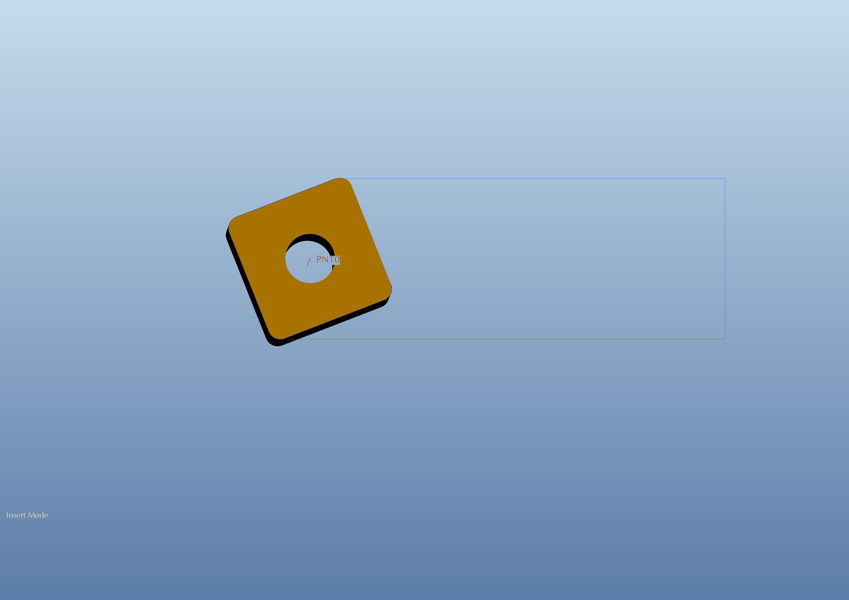
- Mark as New
- Bookmark
- Subscribe
- Mute
- Subscribe to RSS Feed
- Permalink
- Notify Moderator
OK.
Thank you.
- Mark as New
- Bookmark
- Subscribe
- Mute
- Subscribe to RSS Feed
- Permalink
- Notify Moderator
Looks like you need way more rake in that tool insert......... ![]()
- Mark as New
- Bookmark
- Subscribe
- Mute
- Subscribe to RSS Feed
- Permalink
- Notify Moderator
Actually, the only working cutting edge of this insert is the one which is not selected ![]()


