Community Tip - Have a PTC product question you need answered fast? Chances are someone has asked it before. Learn about the community search. X
- Community
- Creo+ and Creo Parametric
- Manufacturing (CAM)
- Re: Surface generated by toolpath
- Subscribe to RSS Feed
- Mark Topic as New
- Mark Topic as Read
- Float this Topic for Current User
- Bookmark
- Subscribe
- Mute
- Printer Friendly Page
Surface generated by toolpath
- Mark as New
- Bookmark
- Subscribe
- Mute
- Subscribe to RSS Feed
- Permalink
- Notify Moderator
Surface generated by toolpath
Unfortunately I have a feature I simply can not figure out how to model in Creo, and I would prefer not to model it in solidworks (which can easily create this feature) and then import to creo.
The feature is a cut on a planar surface (call it X-Y plane for datuming purposes) generated by a 5/16 diameter , 0.06 radius tipped end mill moving in an arc defined from the tip center of the tool. the arc is in the X-Z plane and the tool stays parallel to Z while traversing the arc.
I can not figure out how to create the feature correctly. It must be correct for FEA analysis, and has been vetted by experiment to be vastly superior to our older geometry for making similar features, otherwise I would just use different geometry.
Any tutorials (I could not find any) or tips to create this geometry?
This thread is inactive and closed by the PTC Community Management Team. If you would like to provide a reply and re-open this thread, please notify the moderator and reference the thread. You may also use "Start a topic" button to ask a new question. Please be sure to include what version of the PTC product you are using so another community member knowledgeable about your version may be able to assist.
- Labels:
-
General
- Mark as New
- Bookmark
- Subscribe
- Mute
- Subscribe to RSS Feed
- Permalink
- Notify Moderator
It would be a lot easier to figure out what you are trying to do if there was an image. However, and I could be wrong, but what you are describing sounds like a simple revolved cut. If it's not a complete circle, you could do a revolved cut for the arc it sweeps, then do two cuts at the ends that are full revolutions of the tool profile. Hopefully I'm not being an idiot and misunderstanding what you're asking, but then again, it's happened before...
- Mark as New
- Bookmark
- Subscribe
- Mute
- Subscribe to RSS Feed
- Permalink
- Notify Moderator
unfortunately that is not the case. No 2d profile sweep or revolved cut will create the geometry because if you take a 2d profile of the tool, it is only correct at the 2d location you draw the profile, everywhere else the surface is wrong. Think of it as a boolean subtract between the sweep of the tool and the material. As the tool moves up the arc in the x-z plane, it is not leaving behind a profile at any position that is the 2d cross section of the tool because the leading tip of the tool cuts into the material more than the swept 2d profile does. I may have to snag a solidworks license, draw it, and upload the picture if necessary.
- Mark as New
- Bookmark
- Subscribe
- Mute
- Subscribe to RSS Feed
- Permalink
- Notify Moderator
assuming this is a 2 dimensional cut....
create a datum curve that depicts cut path
then drive a section the shape of your end mill using the curve as a trajectory
finish with the round
- Mark as New
- Bookmark
- Subscribe
- Mute
- Subscribe to RSS Feed
- Permalink
- Notify Moderator
See above. this results in incorrect geometry.
- Mark as New
- Bookmark
- Subscribe
- Mute
- Subscribe to RSS Feed
- Permalink
- Notify Moderator
So as I understand it...
on one leg of the arc, you are generating a circular cut and as you approach the top of the arc, this becomes flat and then transitions back to being circular as you finish out the other leg of the arc?
- Mark as New
- Bookmark
- Subscribe
- Mute
- Subscribe to RSS Feed
- Permalink
- Notify Moderator
Ahh, the ever allusive 3-d solid body sweep. It gets me or I get asked about it once every other year or so.
And there are many more links discussing this under various names.
The closest I have come to it in CREO is to make the end mill as a 3d surface, then pattern it along the cutting path MANY times and then use solidify to cut out the solid.
It's not perfect and can't ever be truly smooth but may be adequate for your needs.
There is a product IDEA for this but I can't find it right off hand.
- Mark as New
- Bookmark
- Subscribe
- Mute
- Subscribe to RSS Feed
- Permalink
- Notify Moderator
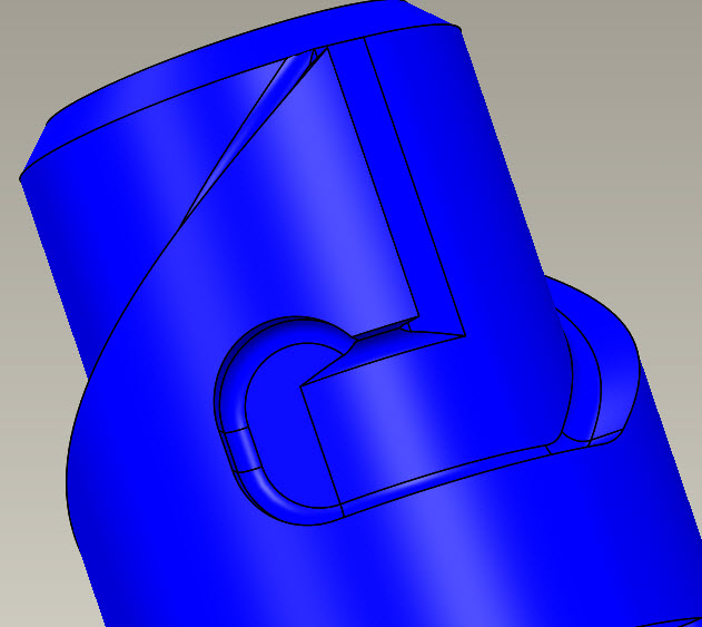
I'm not sure exactly what his geometry looks like but this is one I worked on. We never really got it truly correct to manufacturing.
Sweeping a ball end mill or radius end mill along a 3d path can't be duplicated precisely with Creo.

- Mark as New
- Bookmark
- Subscribe
- Mute
- Subscribe to RSS Feed
- Permalink
- Notify Moderator
The ball mill is by far easier than a flat end
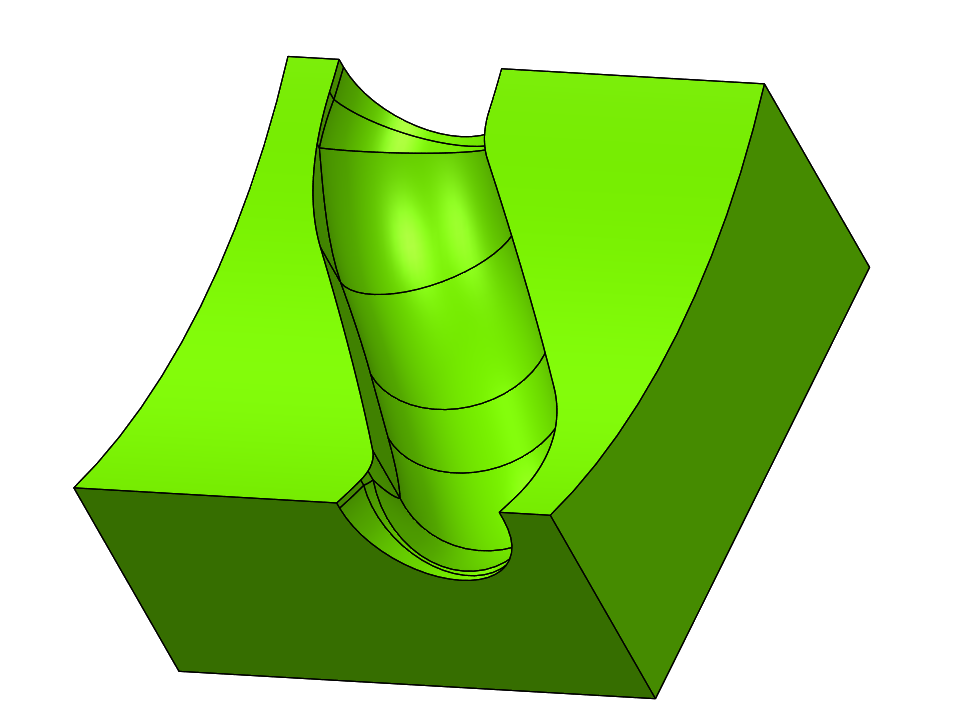
This is what I'm toying with...

- Mark as New
- Bookmark
- Subscribe
- Mute
- Subscribe to RSS Feed
- Permalink
- Notify Moderator
Agreed. It's been a while since I did this. It only comes up occasionally but it's blatantly obvious when you try to accomplish it that you can't get a realistic machined profile.
It's also extremely difficult to explain until you need to generate a specific geometry that you think should be relatively easy.
- Mark as New
- Bookmark
- Subscribe
- Mute
- Subscribe to RSS Feed
- Permalink
- Notify Moderator
Thanks. I was afraid this was the answer. I will probably have to go back to solidworks to build the structural model and then do the production model as an approximation with a drawing note specifying fab method (I hate doing that, and so does our inspection group).
- Mark as New
- Bookmark
- Subscribe
- Mute
- Subscribe to RSS Feed
- Permalink
- Notify Moderator
It can probably be done in a piecewise manner. I did a similar task with wire-frame and surface modeling ages ago. Check "Boundary of the volume swept by a free-form solid in screw motion" ftp://coffeetalk.cc.gatech.edu/pub/gvu/tech-reports/2006/06-19.pdf for hints.
- Mark as New
- Bookmark
- Subscribe
- Mute
- Subscribe to RSS Feed
- Permalink
- Notify Moderator
Holy Moly David!!! Can you dumb that down to a 6th grade level?
You can definitely do it using a curve and patterning a surface of the shape of the cutter along that curve. The more pattern members, the closer you are to perfection.
If anyone attempts the pattern method, I suggest only doing it in the areas that the 3D body cut would make a difference. It will take a large pattern number to get a reasonably smooth surface.
- Mark as New
- Bookmark
- Subscribe
- Mute
- Subscribe to RSS Feed
- Permalink
- Notify Moderator
I recently posted an example where I'd done the cutter-patterning approach for a generated gear form:
- Mark as New
- Bookmark
- Subscribe
- Mute
- Subscribe to RSS Feed
- Permalink
- Notify Moderator
You can just look at the pictures as a way to develop both the terminology and the method for manually creating the subsurfaces. The problem with the pattern method is that the FEM will end up with a great number of tiny elements to follow the small patches.
When I did a this for 4 axes of motion for the motion of a compound surface I started with a tesselated point cloud and a C-program that would accumulate the contributions. Being a simple program I could run it with very small steps and set bins for accumulation as small as I wanted and then take the final result and fit splines and surfaces to it. That way the result will be very smooth and as accurate as one can stand.
I eventually used the same point-manipulation program as a starting point for hydraulic tube bending; taking the XYZ components and producing LRA results and also an LRA to XYZ routine. That was for a stress analysis for determining what happened to errors in bending. It finally got used to generate tube drawings; it wasn't smart enough to create all the auxiliary views, but it got 90% of the work done - about 200 drawings in a half hour. It would be faster now.
- Mark as New
- Bookmark
- Subscribe
- Mute
- Subscribe to RSS Feed
- Permalink
- Notify Moderator
The manufacturing module, if you run "NC Check", generates shaded imagery of what the tool does. This might be helpful if:
(1) It's capable of saving the geometry, which I think it does?
(2) The data it saves is not in some weird proprietary or special format. I fear this one has a bad answer.
(3) The resultant geometry is accurate enough, and not a crude approximation meant for "visualization only".
I'll have to take a look at this.
- Mark as New
- Bookmark
- Subscribe
- Mute
- Subscribe to RSS Feed
- Permalink
- Notify Moderator
I looked into it. It puts out a ".nck" file, which appears to be only for rendering, a "RAYREP" file? Seems to be pretty useless for what we are seeking.


