Community Tip - Your Friends List is a way to easily have access to the community members that you interact with the most! X
- Subscribe to RSS Feed
- Mark Topic as New
- Mark Topic as Read
- Float this Topic for Current User
- Bookmark
- Subscribe
- Mute
- Printer Friendly Page
Electrical Engineering Challenge #2
- Mark as New
- Bookmark
- Subscribe
- Mute
- Subscribe to RSS Feed
- Permalink
- Notify Moderator
Electrical Engineering Challenge #2
Hello,
The problem is as following:
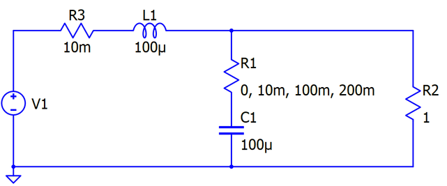
Find currents through R3 and R1 and voltages of R2, R1 and C1 in below circuit:
when:
a)
b)
- Mark as New
- Bookmark
- Subscribe
- Mute
- Subscribe to RSS Feed
- Permalink
- Notify Moderator
Do you REALLY mean this:
Or is mW to be megohms?
- Mark as New
- Bookmark
- Subscribe
- Mute
- Subscribe to RSS Feed
- Permalink
- Notify Moderator
Its ok as in yellow. Not megohms.
- Mark as New
- Bookmark
- Subscribe
- Mute
- Subscribe to RSS Feed
- Permalink
- Notify Moderator
Isn't there a switch right after the generator? Or, since it is not there, should we consider the circuit for an indeterminate time in such conditions, i.e. in the state in which the transient was completed?
- Mark as New
- Bookmark
- Subscribe
- Mute
- Subscribe to RSS Feed
- Permalink
- Notify Moderator
In principle no, we should not consider that transient was completed. You can try doing so If you want, but that will be not the complete solution.
- Mark as New
- Bookmark
- Subscribe
- Mute
- Subscribe to RSS Feed
- Permalink
- Notify Moderator
What do you define as 'the voltage of R1'?
- Mark as New
- Bookmark
- Subscribe
- Mute
- Subscribe to RSS Feed
- Permalink
- Notify Moderator
Anyway, with V2 the voltage across R2 and V3 the voltage across C1, we get:
gives:
so:
Now:
so:
And we find the time functions with:
Enter component values and plot:
When R1=200 mOhm:
For case b:
Following the same procedure as for case a:
And with R1=200 mOhm:
Success!
Luc
- Mark as New
- Bookmark
- Subscribe
- Mute
- Subscribe to RSS Feed
- Permalink
- Notify Moderator
- Mark as New
- Bookmark
- Subscribe
- Mute
- Subscribe to RSS Feed
- Permalink
- Notify Moderator
Now, lets say that someone wants to express voltage across R2 to be function of voltage across C1 and current through L1/R3. Could give the desired equation for this?
- Mark as New
- Bookmark
- Subscribe
- Mute
- Subscribe to RSS Feed
- Permalink
- Notify Moderator
Using laplace we get same results by using IR3(s) and also by using VC1(s).
But you want to express vR2(t) to be the function of vC1(t) and iR3(t). So the rest part of s regions of above are used to evaluate their time functions. They are include delta(t) function, therefore, some techniques are used evaluate the combolution integrals.
Finally, we get the same results for all equations.
Second one is using digital convolution by * . At first digitize all signals of time domain. Also needs some treatment to the delta(t) function.
Finally, also get same results. So, this is the answers of your questions.
- Mark as New
- Bookmark
- Subscribe
- Mute
- Subscribe to RSS Feed
- Permalink
- Notify Moderator
- Mark as New
- Bookmark
- Subscribe
- Mute
- Subscribe to RSS Feed
- Permalink
- Notify Moderator
The network analysis (first case only) can also be done on the basis of the theory of network topology (see: Applied graph theory - W. K. Chen - North Holland ) and the formation of the TABLEAU for the node voltage method (see: Linear and non-Linear Circuits - L. O. Chua, C. A. Desoer, E. S. Kuh - Mc Graw Hill), see following photos:


