Community Tip - Have a PTC product question you need answered fast? Chances are someone has asked it before. Learn about the community search. X
- Subscribe to RSS Feed
- Mark Topic as New
- Mark Topic as Read
- Float this Topic for Current User
- Bookmark
- Subscribe
- Mute
- Printer Friendly Page
How to model bending beam segments?
- Mark as New
- Bookmark
- Subscribe
- Mute
- Subscribe to RSS Feed
- Permalink
- Notify Moderator
How to model bending beam segments?
I have tried to solve differential equations describing the bending behavior of a beam.
The equation is:
EI * w'''''= -q
This is only valid when all the derivatives of w are continuous.
Thus in the case of a point load, a new section is to be defined and conditions are formulated.
(same deflection, same angle, moment equilibrium, shear force equilibrium)
What is going wrong in my file?
- Labels:
-
Calculus_Derivatives
- Mark as New
- Bookmark
- Subscribe
- Mute
- Subscribe to RSS Feed
- Permalink
- Notify Moderator


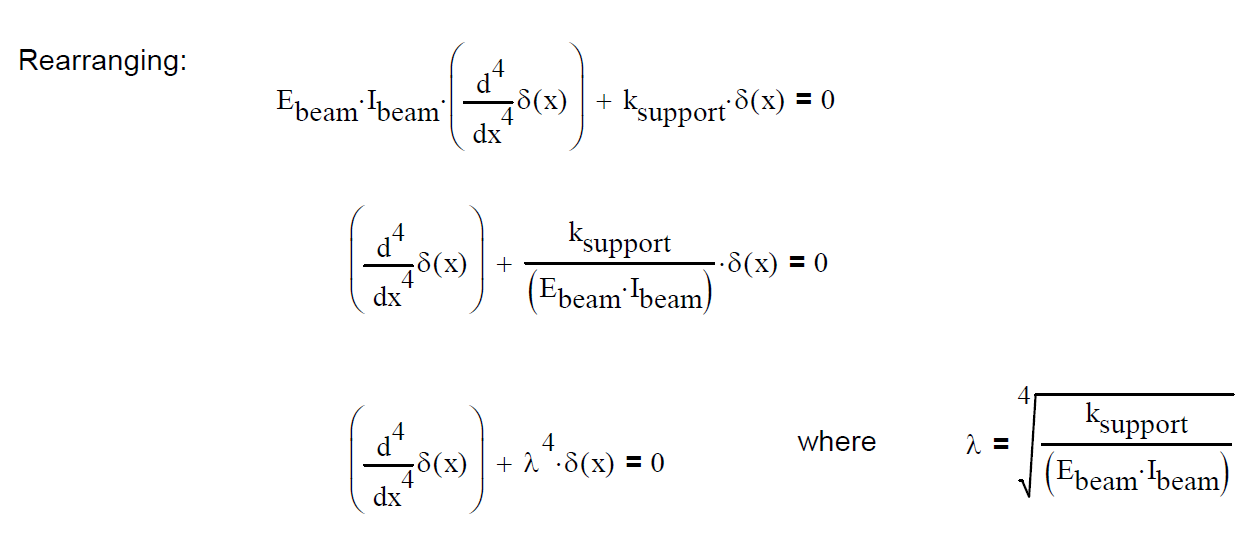
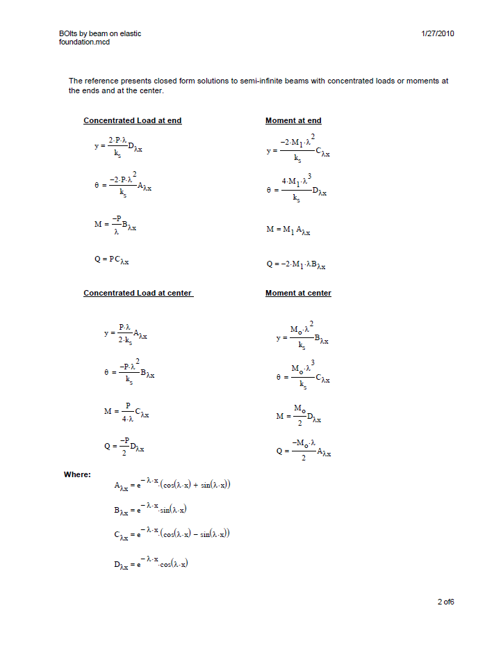
I can't read your file, but I suspect this may help.
- Mark as New
- Bookmark
- Subscribe
- Mute
- Subscribe to RSS Feed
- Permalink
- Notify Moderator
- Mark as New
- Bookmark
- Subscribe
- Mute
- Subscribe to RSS Feed
- Permalink
- Notify Moderator
You just beat me to it ![]()
- Mark as New
- Bookmark
- Subscribe
- Mute
- Subscribe to RSS Feed
- Permalink
- Notify Moderator
Your file has several issues:
- you're setting up two beams, one over L1, the second over L2. It looks like you want to solve for deflection (w1, w2) over the full length of L1,L2; but w1 shouldn't be defined over L2, and w2 shouldn't be defined over L1.
- You define q1(x) and q2(x) but don't solve for them. (Looking at my first response above, q(x) = k w(x), so your basic equations are not right unless you solve for the q1(x) and q2(x) as functions. Then you need two more boundary conditions . . .
- Mark as New
- Bookmark
- Subscribe
- Mute
- Subscribe to RSS Feed
- Permalink
- Notify Moderator
The q1 and q2 are just the loads on the two beams so why do I have to solve them?
How do I tell mathcad that I want w1(x) solved for x=0...L1 and w2(x) for x=L1..L2?
- Mark as New
- Bookmark
- Subscribe
- Mute
- Subscribe to RSS Feed
- Permalink
- Notify Moderator
Where did you get these equations (if not "beam on elastic foundation?) The basic beam bending equation is second order:

When I saw your equation, I immediately recalled an elastic foundation (railroad train tracks on the ground, or a pipe line.) For these cases the ground pushes back--the larger the deflection the stronger the reaction. This is q(x), but it's not constant. For my cases q(x) = k * w(x), where k is N/mm^2. So that is a different problem than what you're working because of the dependence on w(x).
- Mark as New
- Bookmark
- Subscribe
- Mute
- Subscribe to RSS Feed
- Permalink
- Notify Moderator
Your equation is true for a prismatic beam and my equation requires the same assumption:
Taking the derivative of your formula gives us the description of the shear force V(x): EI w'''(x) = V(x)
And taking the derivative again is the change of shear force i.e. the distributed load q(x). EI w''''(x) = -q(x)
The minus sign is a result of the direction at which q is defined positive.
- Mark as New
- Bookmark
- Subscribe
- Mute
- Subscribe to RSS Feed
- Permalink
- Notify Moderator
So you have a beam with an external applied distributed load q(x) and no reactive supports? But you have it "fixed" at both ends and continuous across the middle interface (from your boundary conditions.) Attached is an example of how that might be done.
- Mark as New
- Bookmark
- Subscribe
- Mute
- Subscribe to RSS Feed
- Permalink
- Notify Moderator
I am looking for a way to solve for all kinds of boundary conditions, dimensions and load distributions. And preferably as short as possible so coworkers can easily follow the steps taken. The only reason why I have two beams is that it is now possible to add a pointload by just adding it to the equation of equilibrium shear forces.
Isn't there a way to use my approach? From a mathematical point of view, all the necessary information is presented.
- Mark as New
- Bookmark
- Subscribe
- Mute
- Subscribe to RSS Feed
- Permalink
- Notify Moderator
Smarter people than I are going to have to weigh in; I don't know why your simple system won't solve. I can point out that you haven't solved for the reactions at the ends of your beam, beam shear (first integral of q(x) ) is indeterminate by a constant term, so beam moment (integral of shear) is indeterminate by two terms, linear and constant. That I can solve the problem the "old-fashioned" way indicates it should be solvable and suggests it's an issue with Mathcad.
Maybe finite differences?
- Mark as New
- Bookmark
- Subscribe
- Mute
- Subscribe to RSS Feed
- Permalink
- Notify Moderator
When the displacement is known, the shear force is known as well. And therefor the reactions are known.
When I use the same approach for just 1 beam it works fine as shown in the picture attached.
However, Mathcad does not provide the formula of the deflection. Is that because Mathcad only works numerical at this point? (I know that Maple can)
I expected a formula of the fourth order which I could differentiate twice or thrice to find the expressions for the bending moment and shear force respectively.
- Mark as New
- Bookmark
- Subscribe
- Mute
- Subscribe to RSS Feed
- Permalink
- Notify Moderator
It's not well documented, but the result of odesolve is a spline function, which is why you got the result you circled when you asked for an in-line evaluation.
The attached file (Prime 3.0, which you should be able to open) repeats this.
Shear and moment are defined two ways:
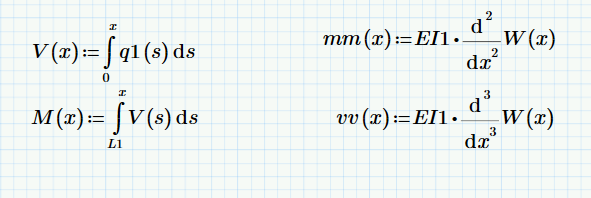
Where q is the linear function you defined and W is the deflection function solved for. Plotting shear:
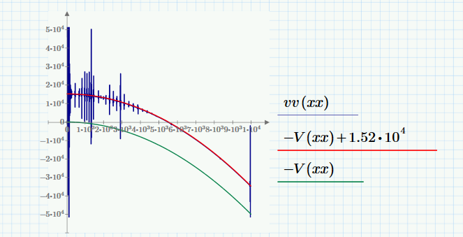
where vv (blue) is the shear by the third derivative of your deflection curve. (W is a spline fit; the third derivative gets spikey.) V (the integral of q(x) ) is green, and it differs by a constant offset (to get the red trace which is on top of the blue.
Plotting moments:
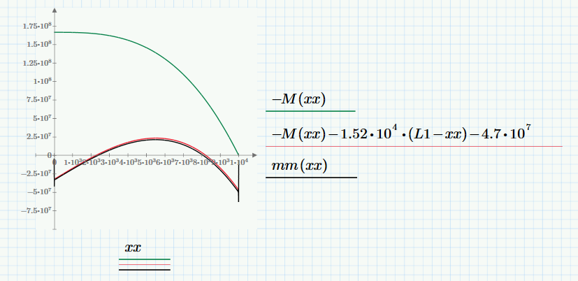
You can see a similar effect.
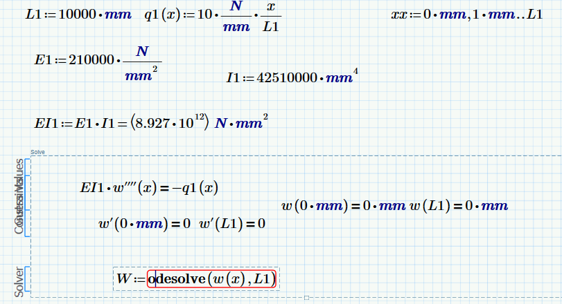
It would be interesting to see if this worked with units or if that's what broke the first attempt. Answer: Apparently
- Mark as New
- Bookmark
- Subscribe
- Mute
- Subscribe to RSS Feed
- Permalink
- Notify Moderator
Thank you very much!
This is very helpfull.
- Mark as New
- Bookmark
- Subscribe
- Mute
- Subscribe to RSS Feed
- Permalink
- Notify Moderator
Your technique would work if units were not involved. (We both showed that.)
If you fight your way thru with units, putting in the integration constants and using the built-in end boundary conditions to solve for them, you wind up with the same answers. Mathcad apparently doesn't have the chops to do that directly, however.
Added a painful unit-tracking solution to the back end. Sorry for the mess.
- Mark as New
- Bookmark
- Subscribe
- Mute
- Subscribe to RSS Feed
- Permalink
- Notify Moderator
You can solve this system this way, but you must non-dimensionalize the problem so Mathcad can deal with it.
New file attached
- Mark as New
- Bookmark
- Subscribe
- Mute
- Subscribe to RSS Feed
- Permalink
- Notify Moderator
My approach indeed lacked units but the problem was coupling two beams.
That problem is not yet solved when using an approach like I suggested in the beginning.
Your way of adding units is however usefull and interesting, thx!
- Mark as New
- Bookmark
- Subscribe
- Mute
- Subscribe to RSS Feed
- Permalink
- Notify Moderator
I do not see how to add a point load to the beam using your method. A point load produces a step change in beam shear, but beam shear is the integral of q. You define q as a distributed load and it defines your fourth order derivative equation. Unless you make a "point load" into a high magnitude short span "distributed load", I don't know how to fit it into your solution. What about a moment applied? How do you write those into your method?
- Mark as New
- Bookmark
- Subscribe
- Mute
- Subscribe to RSS Feed
- Permalink
- Notify Moderator
By introducing two beams, you should be able to incorporate the point load in the interface conditions: V1=V2+F, resulting in continuous equations along each beam.
maybe you could tell me why my new approach, where I write the formulas out, does not work.
- Mark as New
- Bookmark
- Subscribe
- Mute
- Subscribe to RSS Feed
- Permalink
- Notify Moderator
please attach pdf, can't read Prime 3.1.
- Mark as New
- Bookmark
- Subscribe
- Mute
- Subscribe to RSS Feed
- Permalink
- Notify Moderator
- Mark as New
- Bookmark
- Subscribe
- Mute
- Subscribe to RSS Feed
- Permalink
- Notify Moderator
Thanks!
- Mark as New
- Bookmark
- Subscribe
- Mute
- Subscribe to RSS Feed
- Permalink
- Notify Moderator
- Mark as New
- Bookmark
- Subscribe
- Mute
- Subscribe to RSS Feed
- Permalink
- Notify Moderator
Attached sheet shows two segments coupled in two ways:
First way defines functions for EI and q, solves one deflection equation.
Second way tries to solve your two beams coupled. Mathcad chokes on the boundary conditions, but I think it illustrates how to sort out the overall length. The problem is 2 L long, but each w is defined over only one L.
- Mark as New
- Bookmark
- Subscribe
- Mute
- Subscribe to RSS Feed
- Permalink
- Notify Moderator
Thank you, your first method is quite helpful. The second does not work with me I am afraid (see attachment).
I prefer the second method as it is easy to build a complex system.
Your input is much appreciated!
- Mark as New
- Bookmark
- Subscribe
- Mute
- Subscribe to RSS Feed
- Permalink
- Notify Moderator
The second method doesn't work for me either.


