Community Tip - Did you get an answer that solved your problem? Please mark it as an Accepted Solution so others with the same problem can find the answer easily. X
- Subscribe to RSS Feed
- Mark Topic as New
- Mark Topic as Read
- Float this Topic for Current User
- Bookmark
- Subscribe
- Mute
- Printer Friendly Page
Non linear speed control
- Mark as New
- Bookmark
- Subscribe
- Mute
- Subscribe to RSS Feed
- Permalink
- Notify Moderator
Non linear speed control
Hi community , Once again I call on you .
my problem:
I have a mechanism with a non-linear movement
in input, I have a linear displacement, and in output I have an angular displacement
this displacement follows a behavior curve
I want to drive the input with a motor, so here is my problem.
I want to find a max speed value of motor to reach a given angular position. But also that time is linear
that is to say, if I want to go from 0 degrees to 60 degrees (for example) what will be my lowest linear displacement time (constant speed value at output), and what will be my motor control curve
the solution I found is cut the curve with linear parts,but I don't really like it because it's DIY
I don't see the way to get there, maybe with the derivative
If someone has an idea
- Labels:
-
Mechanical_Engineering
- Mark as New
- Bookmark
- Subscribe
- Mute
- Subscribe to RSS Feed
- Permalink
- Notify Moderator
I don't see your attempt in the file you sent.
As far as I understand you are looking for a function
alpha -> speed in rev/s
Can you show the calculations necessary and the result for one or two example angles?
- Mark as New
- Bookmark
- Subscribe
- Mute
- Subscribe to RSS Feed
- Permalink
- Notify Moderator
I'm having trouble explaining myself because I don't speak the language well.
example
if i want to move Alpha =60deg ( row 61 in alpha matrix)
the imput stroke is 32.355mm (row 61 in s matrix)
For 1 motor rev the imput stroke is :0.069mm

and so my motor must do 32.355/0.069 = 468.913 rev
max motor rev speed :0.287 rev/s but is non linear
if i cut the curve, and if that I admit a linear part from 0deg to 10deg
for 10 deg , imput is 2.682mm
2.682/0.069=38.87rev
time is :135.436s for travel 0 to 10deg
and now i assume my curve is linear from 10deg to 60deg
imput stroke 60deg =32.355mm
imput stroke 10deg = 2.682mm
32.355-2.682 = 29.673mm
29.673/0.069= 430.043rev
430.043/0.287=1498s
I don't know if I'm clear, but I want to come to this:
find max speed motor for each target value (row of alpha matrix) for a linear travel time
i want to move 0deg to 60deg with lineartravel, for this I can see that my motor must turn slowly at the beginning, then as quickly as possible at the end
the max speed end is 0.287rev/s so it is this value which is measured to evaluate the speeds at small angles
sorry for these confusing explanations, I think there may be a way with the derivative, but I can't find anything
- Mark as New
- Bookmark
- Subscribe
- Mute
- Subscribe to RSS Feed
- Permalink
- Notify Moderator
English isn't my native language, too (I'm German speaking) but as my French is even worse (not to say non-existent) English seems to be the best choice anyway (a big "thanks!" to Google translate from me at this point). Furthermore the reason for me not understanding exactly what you are looking for may also be because I am not a mechanic guy and so my lack of expertise sure adds to the uncertainty.
The times you calculate for the travel from 0 t0 10 degree or from 10 to 60 degree are calculate for maximal motor speed.
When you demand "linear travel time" I guess you mean that you want to control the motor in a way so that the angle should change at constant speed, correct? (A constant motor speed would mean that the displacement s changes at constant speed which is not what you want).
The i.gear=29 means that the transmission (reduction) ratio is 1:29, so we never deal with the 500 rpm, right?
But why are you asking for the maximal motor speed of that travel - its determined by the motor characteristics and is 0.287 rev/s in any case as I understand it.
I am not absolutely sure, but I guess it could be beneficial to create a true function alpha(s)=.. or maybe the inverse s(alpha)=...
Doing so could either be done by interpolation (linear or spline) or by a fitting function. In case of the latter it would help if you know some characteristics about the relationship between s and alpha to chose the appropriate type of function for the regression.
- Mark as New
- Bookmark
- Subscribe
- Mute
- Subscribe to RSS Feed
- Permalink
- Notify Moderator
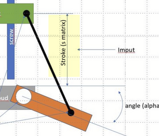
I drawing quickly this:
the goal is send an electronics command for move the orange part, for this i have two way.
First:
JOG command : the simple impulsion give a 1deg step at max speed motor:
Second:
a give a target : for example 30deg : here a need an algorithm with move the orange part with constant velocity. and this velocity must be use a max speed motor.
as the purpose is to control the electronics, I do not think that the integrated functions of mathcad like fitloees can be used
Buts maybe i'm wrong ?
- Mark as New
- Bookmark
- Subscribe
- Mute
- Subscribe to RSS Feed
- Permalink
- Notify Moderator
Seeing the kinematics seems to make it clearer for me.
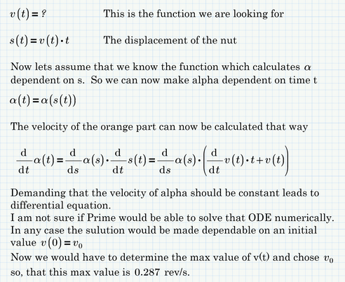
The goal is to move the orange part to a specific angle position as fast as possible but with constant speed (of the orange part) which means variable speed of the nut.
The relationship between the motor speed and the speed of the nut is linear and the max speed of the motor is about 0,287 rev/s.
Is this correct so far?
Is the desired movement always from the zero degree position to a certain angle or can the starting point be different to zero? Lets say something like "move the orange part from 70° position to 25° position".
What still confuses me is this:
Your example (with the 10 degree angle) using constant motor speed of 0,287 rev/s moves the nut for a distance of 2.682 mm in 135.436 seconds. Thats a speed of 0.02 mm/s.
As I understand it thats the constant (maximal) speed of the nut if the motor runs at full speed
But what is the meaning of the v.vis_vss33 = 0.575 mm/s shown in your sheet??
- Mark as New
- Bookmark
- Subscribe
- Mute
- Subscribe to RSS Feed
- Permalink
- Notify Moderator
yes, you have undestand !
"Seeing the kinematics seems to make it clearer for me.
The goal is to move the orange part to a specific angle position as fast as possible but with constant speed (of the orange part) which means variable speed of the nut"
yes
"The relationship between the motor speed and the speed of the nut is linear and the max speed of the motor is about 0,287 rev/s.
Is this correct so far?"
yes
"Is the desired movement always from the zero degree position to a certain angle or can the starting point be different to zero? Lets say something like "move the orange part from 70° position to 25° position"
yes
For the rest I may have made typing errors.
in my sheet:
the screw is : Ø6x2
for one rev, the nut travel 2mm thanks to the helical connection
the max speed motor is 500rpm
the max speed output gearbox is 0.287rev/s (with mechanical ratio i=29)
v.vis_vss33 = 0.575 mm/s mean the nut velocity translation
- Mark as New
- Bookmark
- Subscribe
- Mute
- Subscribe to RSS Feed
- Permalink
- Notify Moderator
> for one rev, the nut travel 2mm thanks to the helical connection
One revolution of the screw, after the gear box, not one revolution of the driving motor, right?
> v.vis_vss33 = 0.575 mm/s mean the nut velocity translation
Still unclear to me. Is this a fictive velocity of the the nut if there would be no gear box and the real nut velocity is 0,02 mm/s as shown??
Anyway, here are my thoughts so far and I in no way claim that I am on the correct way with them. At least its an explanation why I thought it might be helpful to have a function alpha(s), either by interpolation or by regression. Of course as you probably know all dimensions of your mechanics, you may also derive the exact function alpha(s) using basic geometry.
BTW, your drawing doesn't seem to match the values given in you sheet.
According to your drawing small values of s would yield larger angles. in your sheet the opposite is the case!
- Mark as New
- Bookmark
- Subscribe
- Mute
- Subscribe to RSS Feed
- Permalink
- Notify Moderator
Thanks ! i will watch carefully your way
> for one rev, the nut travel 2mm thanks to the helical connection
One revolution of the screw, after the gear box, not one revolution of the driving motor, right?
Yes
if you do not understand for the motor, it is me who explains badly, I made a new drawing
for one screw rev, the nut move to 2mm
0.02 this must be a mistake on my part
- Mark as New
- Bookmark
- Subscribe
- Mute
- Subscribe to RSS Feed
- Permalink
- Notify Moderator
0.02 this must be a mistake on my part
I guess the error was here
as you used the displacement per motor revolution and not per screw rev.
So it seems that the task is clear to me, unfortunately not the way how to solve it. I just became doubts about the method I sketched above as I would have two independent parameters to chose - the initial value for the velocity AND the constant velocity of alpha. It looks to me thats one too much. Maybe I'll see clearer tomorrow or one of my fellows here in he forum has a good idea 😉
BTW, what about my criticism that in your drawing small values of s would yield larger angles while in your sheet its the other way round. I guess that s should rather be the distance of the nut from a certain point near the motor/gear.
I made a model according to that but could not find dimensions which would yield results similar to those given in your sheet. So I suppose the real kinematics are somewhat more complicated and the drawing was just a simplification.
- Mark as New
- Bookmark
- Subscribe
- Mute
- Subscribe to RSS Feed
- Permalink
- Notify Moderator
I wrote how I determine the curve
i try to make alpha function with Mathcad loess
I'm really sorry for having posed the problem so badly in the 1st messages
I too hope that the night will help me
- Mark as New
- Bookmark
- Subscribe
- Mute
- Subscribe to RSS Feed
- Permalink
- Notify Moderator
Ah, now alpha and s are defined differently compared to your first drawing!
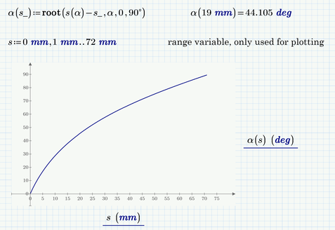
Personally I prefer working with functions and not with vectors. The function you create (approximate) which gives us the displacement s for any angle alpha could be derived a bit easier and directly that way:
The inverse function (which we presumably need) could be probably derived in an exact way, but its much easier to either use a solve block or the numeric "root" command 😉
Now we have functions we could integrate, take the derivative of or use in an odesolve block, but I still don't know how to solve your initial problem.
- Mark as New
- Bookmark
- Subscribe
- Mute
- Subscribe to RSS Feed
- Permalink
- Notify Moderator
I'm used to using vectors, for a mechanic it's more natural. I understand that for a mathematician functions are more natural Anyway thank you for your help. Your writing is simpler, more effective, thank you for that. I don't have the skills to solve this problem. I can't find a way
- Mark as New
- Bookmark
- Subscribe
- Mute
- Subscribe to RSS Feed
- Permalink
- Notify Moderator
My point was that you created vectors of values using the exact mathematical functions and then you used a fit function to apptroximate the function you already had used anyway.
Of course you could use the functions I provided to create a couple of vectors if you need them. But to solve your problem, I guess we need continuous functions.
On the other other hand - the problem may be a discrete one and no a continuous one as you probably can't control your stepper in a continuous way. Not sure how to handle that.
- Mark as New
- Bookmark
- Subscribe
- Mute
- Subscribe to RSS Feed
- Permalink
- Notify Moderator
>On the other other hand - the problem may be a discrete one and no a continuous one as you probably can't control your stepper in a continuous way
Yes is right!
so if I dichotomize the curve to obtain approximate linear portions that may be sufficient🤔
- Mark as New
- Bookmark
- Subscribe
- Mute
- Subscribe to RSS Feed
- Permalink
- Notify Moderator
You can find a function of motor speed vs position that linearizes the angular travel in time.
See attached:
- Mark as New
- Bookmark
- Subscribe
- Mute
- Subscribe to RSS Feed
- Permalink
- Notify Moderator
Thank you very much Fred! Thanks to you I learn a lot in the use of mathcad. It's silly but your sheet made me discover the global variable. I did not understand everything in your sheet, and I will try to deepen! this seems to match what you are looking for. Thank you again to all for making me progress in the use of Mathcad, but not only! My math level is also progressing with you, that's a very good thing!😃
- Mark as New
- Bookmark
- Subscribe
- Mute
- Subscribe to RSS Feed
- Permalink
- Notify Moderator
Hello Fred can you explain this to me this function
And why mathcad have a probleme with A
Thanks
- Mark as New
- Bookmark
- Subscribe
- Mute
- Subscribe to RSS Feed
- Permalink
- Notify Moderator
excuse me for poly_fit, I am an idiot
- Mark as New
- Bookmark
- Subscribe
- Mute
- Subscribe to RSS Feed
- Permalink
- Notify Moderator
There is a simple explanation: I only have Prime Express. So a lot of the functions are disabled. Sometimes the choice of what's disabled are strange:
The function polyfit is particularly useful, it will fit a polynomial to data and you can choose what order you want. It's also one of the ones that Express doesn't have, so I set out to build a least squares fit to a polynomial. Attached is a Prime 4.0 version that 7.0 can open. The expression

- Mark as New
- Bookmark
- Subscribe
- Mute
- Subscribe to RSS Feed
- Permalink
- Notify Moderator
As Fred Kohlhepp already mentioned, using polyfitc function, you can use to do next step mathematically.
Tokoro.


