Community Tip - Stay updated on what is happening on the PTC Community by subscribing to PTC Community Announcements. X
- Subscribe to RSS Feed
- Mark Topic as New
- Mark Topic as Read
- Float this Topic for Current User
- Bookmark
- Subscribe
- Mute
- Printer Friendly Page
K Factor Grayed Out
- Mark as New
- Bookmark
- Subscribe
- Mute
- Subscribe to RSS Feed
- Permalink
- Notify Moderator
K Factor Grayed Out
Hello Everyone. Here's a question about the K Factor in a component.
When I open a part, I go to the EDIT menu and select SETUP, from there I'm able to select the bend allowance and select my K/Y factor
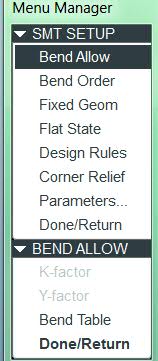
but they show grayed out...
If I select PARAMETERS instead
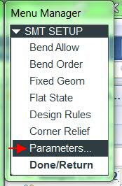
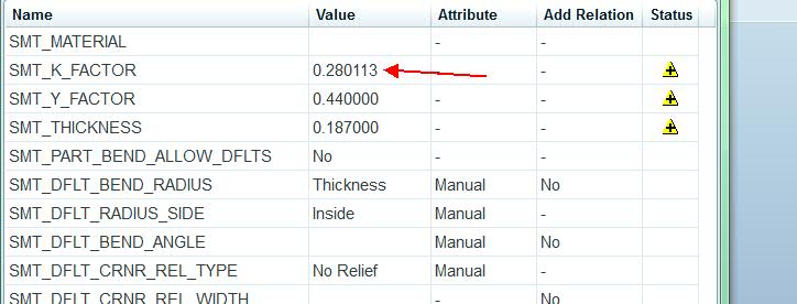
I can see what the current value is. I get a message that the value has been edited from the default.
I can reset the whole table by right clicking
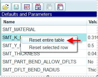
But still, I'm not able to change the values.
Now, if I select a flange and EDIT DEFINITION, I can control the bend allowance independently...
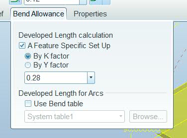
Am I doing something wrong? Do you think these options are grayed out because the part was modeled in certain way or because my config is set up to gray it?
If I change it in every feature, would it have the same effect?
Thanks in advance.
I'm using the Windows 7 64 bit, creo elements pro 1.0 (WF5) M170.
This thread is inactive and closed by the PTC Community Management Team. If you would like to provide a reply and re-open this thread, please notify the moderator and reference the thread. You may also use "Start a topic" button to ask a new question. Please be sure to include what version of the PTC product you are using so another community member knowledgeable about your version may be able to assist.
- Labels:
-
General
- Mark as New
- Bookmark
- Subscribe
- Mute
- Subscribe to RSS Feed
- Permalink
- Notify Moderator
Hello Alan and welcome to the forum.
I am just guessing here but if the Y-factor has a value, the K-Factor may not be available.
Maybe you can chase it with the following information.
This is the relations built into Creo 2.0 sheetmetal, empty part -
/* The following relations make the bend allowance parameters */
/* of part to be dependent on the assigned material, if the value */
/* of the parameter SMT_UPDATE_BEND_ALLOW_INFO is YES. */
/* If you remove or change these relations, the check box */
/* 'Use assigned material to define the value of the bend */
/* allowance parameters' in the Bend Allowance category */
/* in sheet metal Preferences dialog box might stop working. */
if ( SMT_UPDATE_BEND_ALLOW_INFO == YES && exists("PTC_MATERIAL_NAME") )
if ( string_length( material_param("BEND_TABLE") ) > 0 )
SMT_PART_BEND_TABLE_NAME = material_param("BEND_TABLE")
endif
if ( material_param("INITIAL_BEND_Y_FACTOR") > 0.0 )
SMT_PART_BEND_ALLOW_FACTOR_TYPE = "Y FACTOR"
SMT_PART_BEND_ALLOWANCE_FACTOR = material_param("INITIAL_BEND_Y_FACTOR")
endif
endif
SMT_DFLT_BEND_RADIUS = SMT_THICKNESS
SMT_DFLT_CRNR_REL_WIDTH = SMT_THICKNESS
SMT_DFLT_CRNR_REL_DEPTH = SMT_THICKNESS
SMT_DFLT_BEND_REL_WIDTH = SMT_THICKNESS
SMT_DFLT_BEND_REL_DEPTH = SMT_THICKNESS * 2.0
SMT_GAP = SMT_THICKNESS * 0.5
SMT_DFLT_EDGE_TREA_WIDTH = -SMT_GAP
SMT_DFLT_MITER_CUT_WIDTH = SMT_GAP
SMT_DFLT_MITER_CUT_OFFSET = SMT_THICKNESS * 1.1
- Mark as New
- Bookmark
- Subscribe
- Mute
- Subscribe to RSS Feed
- Permalink
- Notify Moderator


