Community Tip - Your Friends List is a way to easily have access to the community members that you interact with the most! X
- Subscribe to RSS Feed
- Mark Topic as New
- Mark Topic as Read
- Float this Topic for Current User
- Bookmark
- Subscribe
- Mute
- Printer Friendly Page
trajpar
- Mark as New
- Bookmark
- Subscribe
- Mute
- Subscribe to RSS Feed
- Permalink
- Notify Moderator
trajpar
I have attempted to use trajpar and it appears to be turned off for Creo 3.0. Is trajpar turned off?
Is there a config.pro setting that allows for this feature to be used?
This thread is inactive and closed by the PTC Community Management Team. If you would like to provide a reply and re-open this thread, please notify the moderator and reference the thread. You may also use "Start a topic" button to ask a new question. Please be sure to include what version of the PTC product you are using so another community member knowledgeable about your version may be able to assist.
- Labels:
-
General
- Mark as New
- Bookmark
- Subscribe
- Mute
- Subscribe to RSS Feed
- Permalink
- Notify Moderator
Hi,
and see attachment.
MH
Martin Hanák
- Mark as New
- Bookmark
- Subscribe
- Mute
- Subscribe to RSS Feed
- Permalink
- Notify Moderator
In Creo 3, trajpar doesn't work unless you press this button:


- Mark as New
- Bookmark
- Subscribe
- Mute
- Subscribe to RSS Feed
- Permalink
- Notify Moderator
I realized my mistake in using trajpar. I setup a relation after creating the feature. This needs to be done while creating the feature.
- Mark as New
- Bookmark
- Subscribe
- Mute
- Subscribe to RSS Feed
- Permalink
- Notify Moderator
Correct. Trajpar is only valid in VSS
- Mark as New
- Bookmark
- Subscribe
- Mute
- Subscribe to RSS Feed
- Permalink
- Notify Moderator
Dear Experts,
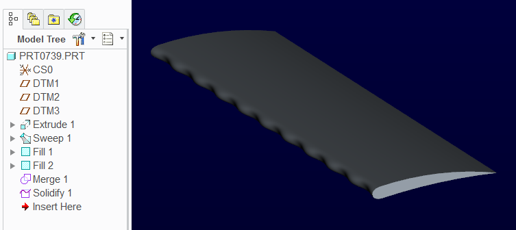
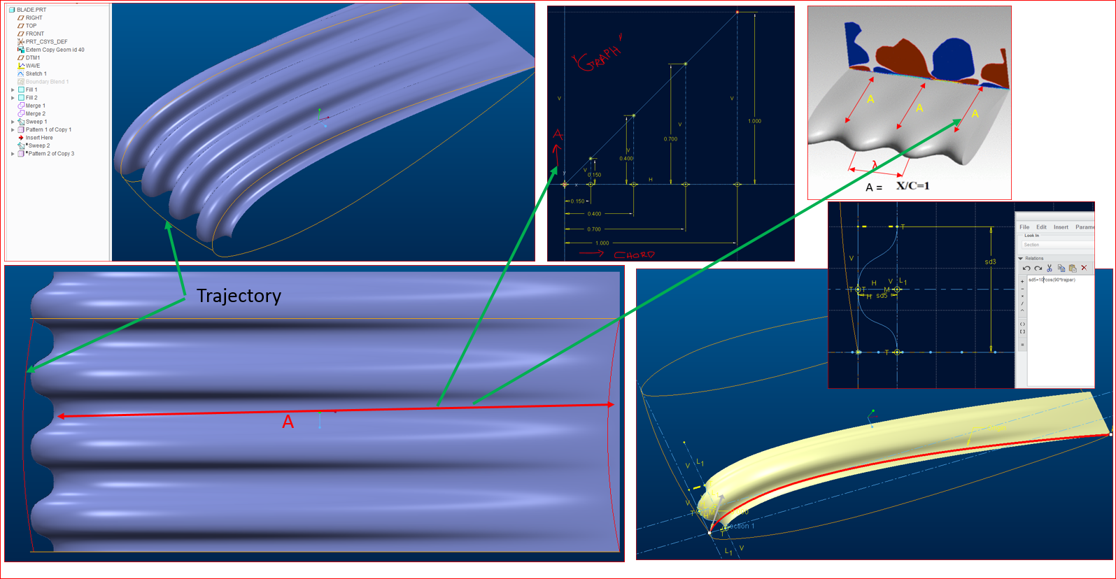
Could you please help me to create the below mentioned areofoil profile? I am new to the " Trajpar"( didn't understand the logic)...
I could able to generate to generate leading edge bumps but failed to create the diminishing geometry at trailing edge(by varying chord).
Please share some advice on this!
Note:-
1. "A" is a variable parameter ( example: @ 10% of chord, @ 40% of chord,@ 70% of chord,@ 100% of chord)

Thanks,
Hari
----------------------------------------------------------------------------------------------
"Share your knowledge. It is a way to achieve immortality.” - Dalai Lama.
- Mark as New
- Bookmark
- Subscribe
- Mute
- Subscribe to RSS Feed
- Permalink
- Notify Moderator
Trajpar is simply a "function" that lets you create a variable ranging from 0 to 1 which can be used in a formula.
How you want to manipulate that formula along a path is up to you.
In this case you want an undulating edge. This is best accomplished with a sine or cosine function. Angles are treated as 1 degree with trajpar.
- Mark as New
- Bookmark
- Subscribe
- Mute
- Subscribe to RSS Feed
- Permalink
- Notify Moderator
Have a look at this file: Creo 2.0 parametric commercial version
This is very straight forward to show the Trajpar function in the Sweep feature.

- Mark as New
- Bookmark
- Subscribe
- Mute
- Subscribe to RSS Feed
- Permalink
- Notify Moderator
Trajpar() is a function that is used to evaluate along a curve. Each curve has a start point and an end point. Trajpar() at the start point returns '0' and and at the end returns '1' This lets the result that is using trajpar() adapt as it progresses along the curve. When the curve is selected you are given the choice as to which end to start from.
If you want something to happen 50 times along a curve you would have an equation 50*trajpar()
Creo Parametric Help Center on trajpar examples.
- Mark as New
- Bookmark
- Subscribe
- Mute
- Subscribe to RSS Feed
- Permalink
- Notify Moderator
Funny, someone else was modeling the same wing:
- Mark as New
- Bookmark
- Subscribe
- Mute
- Subscribe to RSS Feed
- Permalink
- Notify Moderator
Dear Sir,
Thank you Very much for your guidance...![]()
Could you please guide me on following points?
- Can we do the pattern of “humpback” profile through the leading curve and trailing edge?
- Can we change the sweep length according to “Graph”( ex. 15% chord,40 % chord etc..)
- My intent is to remove the material from aerofoil as per humpback profile and make it sold.

If you have some free time kindly guide me …
Please find the attached CAD model for your information..
Regards,
Hari
----------------------------------------------------------------------------------------------
"Share your knowledge. It is a way to achieve immortality.” - Dalai Lama
- Mark as New
- Bookmark
- Subscribe
- Mute
- Subscribe to RSS Feed
- Permalink
- Notify Moderator
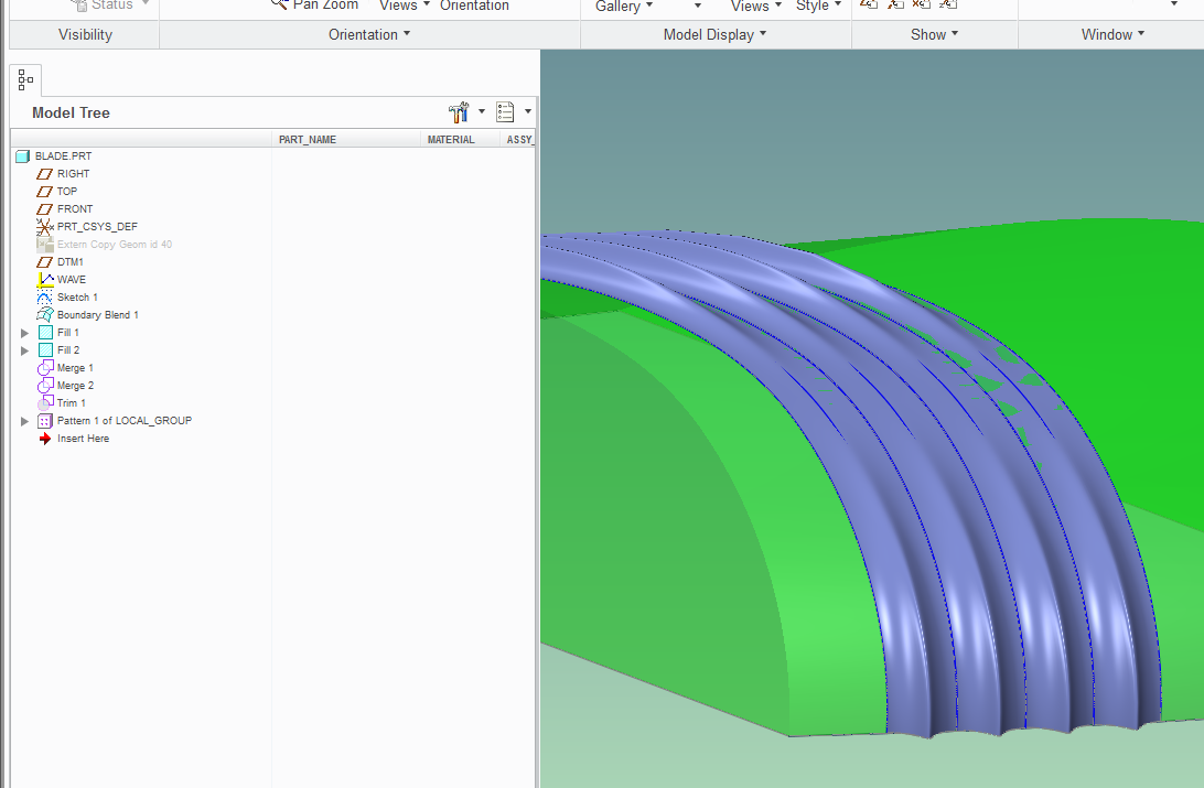
I will attempt to help - by an example model based on what you submitted (Creo 2.0, M230):

I am sure there are other, most likely better ways of doing this, but please open the file and try to follow along with my "method":
If you want to pattern the "bulge stripes" along the wing, your sweep trajectories have to follow the boundary blend that describes the underlying shape. One way to do that is to use an intersect curves generated by a plane offset from the edge of the wing. In the pattern instances, that offset distance will vary.
Also, I make use of sweep guide "chains" that carry with them the tangency information.
I am not sure actually what you want to do with the "WAVE" graph, but I put into the sweep a variance based on a graph. In my opinion, using the cosine function makes it rather convoluted how the amplitude of the "bulge" varies; still it illustrates how it bulges more at the leading edge, then disappears, then another bump as the bulge makes its way towards the trailing edge.
Like I said - this example is for illustration, and it needs a lot more work. For example, you will notice that the bulge stripes are matched at the seams, but not all the way from the leading/trailing edges of the wing! Perhaps that could be solved by having the sweep do a nearly "full loop", then trimming and re-attaching a relatively simple trailing edge... Anyway, this is a fun exercise, I'll spend a bit more time with it on the weekend and I wish you good luck!
- Mark as New
- Bookmark
- Subscribe
- Mute
- Subscribe to RSS Feed
- Permalink
- Notify Moderator
- Mark as New
- Bookmark
- Subscribe
- Mute
- Subscribe to RSS Feed
- Permalink
- Notify Moderator
Respected Sir,
My intention for using the Graph option ( not sure will it help ) is to control the "chord length "( leading edge to trailing surface blending disappearing plane) in future with different values ( 70% , 40% , 15% etc...) by using program (by adding a parameter(" chord percentage")....
i.e, I would like to automate or regenerate the model( bulge stripes) with different chord length( 70% , 40% , 15% etc...)

Thank you sir for spending time to guide me....
Best Regards,
Hari
--------------------------------------------------------------------------------------------------
"Share your knowledge. It is a way to achieve immortality.” - Dalai Lama
- Mark as New
- Bookmark
- Subscribe
- Mute
- Subscribe to RSS Feed
- Permalink
- Notify Moderator
Hari,
Attached is an older PTC training file that shows use of graphs to drive geometry. The model is of a hummingbird. The "wing" geometry may be of interest to you.
Regards,
Dan N.
- Mark as New
- Bookmark
- Subscribe
- Mute
- Subscribe to RSS Feed
- Permalink
- Notify Moderator
Dear Daniel ,
Thank you very much for providing the example file and it will definitely help me to execute my task.
Please accept my sincere gratitude for helping me on crisis.
Kind Regards,
Hari
----------------------------------------------------------------------------------------------
"Share your knowledge. It is a way to achieve immortality.” - Dalai Lama.


