1-Visitor
January 14, 2016
Question

Adding lines to dimension angles

  • January 14, 2016
  • 3 replies
  • 4743 views

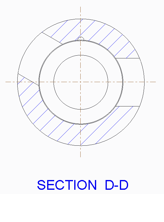
I need to dimension the angle which a port was created.  The dimension line would be to the middle of the port but is obviously not modeled and created this way.  If I try adding the line in the drawing there are no constraint's.  I need the line to be from the center of the tube to the center of the rectangular port.  See attached.

SECTION ANGLES.png


This thread is inactive and closed by the PTC Community Management Team. If you would like to provide a reply and re-open this thread, please notify the moderator and reference the thread. You may also use "Start a topic" button to ask a new question. Please be sure to include what version of the PTC product you are using so another community member knowledgeable about your version may be able to assist.

3 replies

23-Emerald III
January 14, 2016

There are a few options, none of which should include sketching in the drawing!!!

If there is an axis in the cut, show it and use it to dimension to.

If there are other axis through the center of the part, you can edit the attachment of one of those and make it parallel to the rectangular cut.

If you can modify the model, use a construction line or a centerline to the cut sketch so you can dimension it as you want the drawing to show it.

I can think of several others but these are really the best options.

dbolden1-VisitorAuthor
1-Visitor
January 14, 2016

I guess a further problem lyes in that the drawing is created from an assembly and I cannot get the construction line that I created in the sketch to show up in the drawing.  I tried using the filters in the bottom right corner....nothing.  I went to the Datum tab inside the Show Model Annotations and don't see the axis line I have in my part model.

It is a mess but I can get my angle from the part creation to come in.  It also shows EVERY other dimension in the part.  I am lucky on this one that I can find what I want.  I would still need to that the axis line there to show dim too.

1-Visitor
January 14, 2016

Your best option is to go back into the model and into the sketch for the feature and add a "Datum Point" in the center of the feature and that will create the "extruded" axis through the middle of the feature.

Hope this helps,

Shane V.

dbolden1-VisitorAuthor
1-Visitor
January 14, 2016

If I drop a datum point, how do I get it to give me the extruded axis?  I have a construction line throught the middle of the feature but it doesn't show up anywhere.  I need to dimension the overall width as well as the axis to an edge.  I have this in there but cannot find it through the clutter of dimensions if I look at "component" in the search filter. 

1-Visitor
January 14, 2016

Are you adding the Datum Point inside of the Sketch for creating the feature?. Not as a feature on its own after the cut/extrude is created? If it is inside of the sketch feature it should "extrude" along with the cut/extrude feature. Does this make sense?

1-Visitor
January 15, 2016

An option would be to create an axis on the existing hole and show that in your drawing for the desired dimension.  Donald, if you want to hit me with a PM, I'd be happy to create an online meeting and review options with you.    dimension.png

dbolden1-VisitorAuthor
1-Visitor
January 15, 2016

I tried to send a PM not sure if you got it.  It says sent but the message remains on the screen.  I didn't want to keep whacking the send button if it sent.

a live meeting would be great.   I have tried every suggestion people had had to no avail.  Keep in mind that the cut I am trying to dimension is a rectangular shape, not round.  I think this is why the axis line suggestion keeps popping up.

My email is -

1-Visitor
January 15, 2016

Well if anyone can help you it will be Hippe. He always has to steal my thunder!! Haha.

He will take good care of you though.