

Did You Know? PTC Creo 3.0 Simulate Supports Parts Created in Other CAD Systems
When you need to bring a model into your assembly that was designed using a different CAD system, you don’t want to lose important data, and you especially don’t want to deal with being unable to load the file into your assembly at all. With PTC Creo 3.0, you can load parts into your assembly that were not designed using PTC Creo. Then, you can use PTC Creo Simulate to perform analyses, meshing, and optimization on the whole assembly--native and non-native parts. In this post, a PTC expert explains how the feature works.
In Creo 3.0, major enhancements now enable true heterogeneous assemblies. This is a major enhancement that allows PTC Creo to open 3D models in Native NX, Catia, SolidWorks, SolidEdge, Inventor and JT formats, without creating intermediate or new PTC Creo files. That means you can analyze these components, or their assemblies, in PTC Creo Simulate as if they were native to PTC Creo models.
Shown below is an assembly called Frame. By clicking Applications > Simulate, and we can leverage the assembly to perform an analysis.
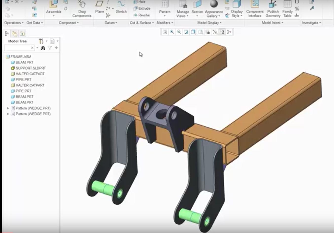
This assembly contains three parts that were designed outside of PTC Creo.
To help identify the components that are non-PTC Creo models, just look at the actual designated file name, as well as its extension, in the Model Tree. In the Model Tree shown in the example above, the SUPPORT component is designated as SLDPRT, which indicates that it is a SolidWorks file. The same can be said for the Catia files; in this case, the HALTER CATPART files.
Once in PTC Creo, these components act like they are native files. You can apply loads, constraints, and define material properties for each of those components.
To assign a material to non-native components, just follow these steps: In the Model Tree, expand Material Assignments. If a material has already been assigned to your assembly, right-click the material assignment and click Edit Definition.
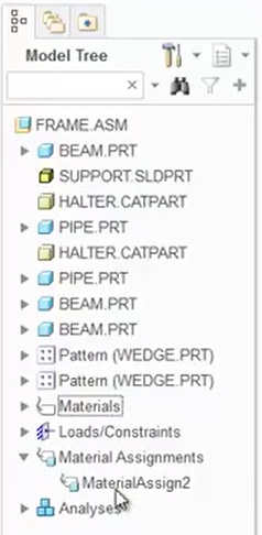
By right-clicking MaterialAssign2 and clicking Edit Definition, you can assign the material definition to the entire assembly, including non-native parts.
On your keyboard, press Ctrl, and click any non-native parts (in our example, the support and the two halter parts). At this point, the parts have been added into the collector. Now, every component in the assembly has been assigned the material definition.
Once the materials are assigned, create a mesh by clicking Refine Model > AutoGEM, just to show that the assembly can be meshed successfully.
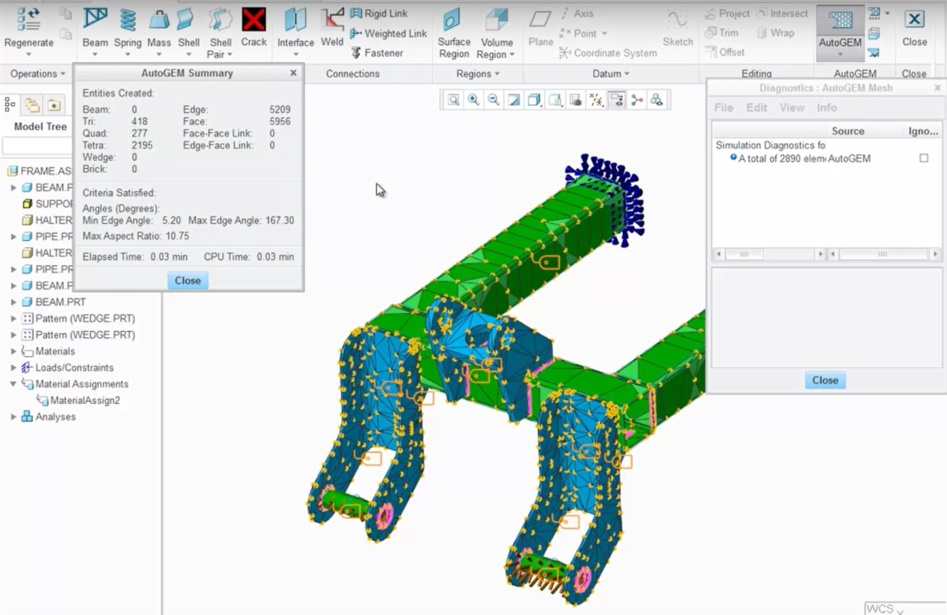
After non-native parts are added to the assembly, you should be able to mesh the entire assembly.
With the assembly having its defined constraints, loads, and material properties, perform the analysis by clicking Home > Analyses and Studies. Once the analysis has been performed, the results can be reviewed.
In this case, we look at the maximum displacement. To do this, on the Analysis and Design Studies dialog, click the button to Review the results of the design study or finite element analysis. Set up the analysis definition on the Result Window Definition dialog. Click OK and Show. As shown below, the analysis runs on the entire assembly, including parts that were not designed using PTC Creo.
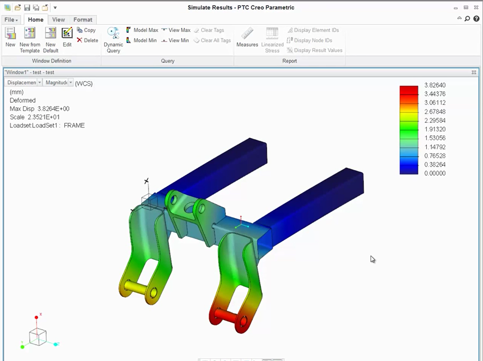
After non-native parts are added to the assembly, an analysis can be performed on the entire assembly.
PTC Creo used all of the components in the assembly, regardless of whether they came from another CAD application.
Throughout the PTC Creo environment, various analysis reports will reference non-native PTC Creo models with their proper names and identifiers. PTC Creo can easily manage these files within the PTC Creo environment. And, leveraging the power of PTC Creo Simulate, you can analyze, verify and improve the overall design.
To learn more about PTC Creo Simulate’s support of non-native file types check out our video tutorial (“Simulate Support for Truly Heterogeneous Assemblies”).
Stay tuned to our “Did You Know” blog series as we cover more exciting, new enhancements in PTC Creo 3.0.
Have some ideas about what PTC Creo product features you’d like to learn more about? Send me a message or leave a comment below and we’ll write up the best ideas from the community. Thanks for reading, looking forward to all of your feedback!
In case you missed it, see what’s new and check out our recent Did You Know posts covering PTC Creo 3.0 enhancements:
- Did You Know? Interactive Surface Design Extension (ISDX)
- Did You Know? PTC Creo 3.0: Intelligent Fastener Extension Part 3
- Did You Know? PTC Creo 3.0: Intelligent Fastener Extension Part 2
This thread is inactive and closed by the PTC Community Management Team. If you would like to provide a reply and re-open this thread, please notify the moderator and reference the thread. You may also use "Start a topic" button to ask a new question. Please be sure to include what version of the PTC product you are using so another community member knowledgeable about your version may be able to assist.