1-Visitor
July 8, 2016
Question

Formed Sheetmetal Corner (Rounded Solid)

  • July 8, 2016
  • 5 replies
  • 5319 views

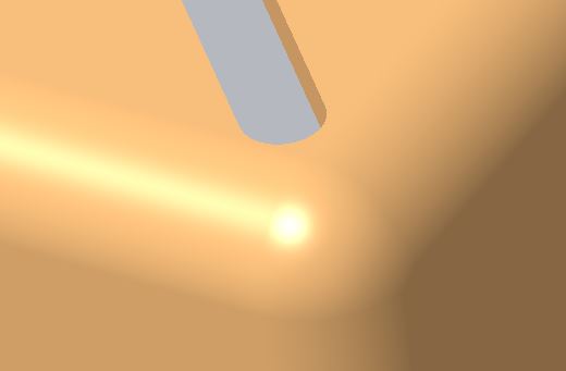
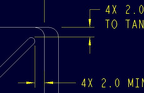
I did this years ago in Wildfire and sheetmetal did not know how to flatten it, but it was good enough.  The part was originally a solid model (shown below) and am attempting to create filled corners in sheetmetal because the part is made that way.  See the pic below for solid model corner.

Solid Part Corner.JPG    Solid Part Corner Dwg.JPG

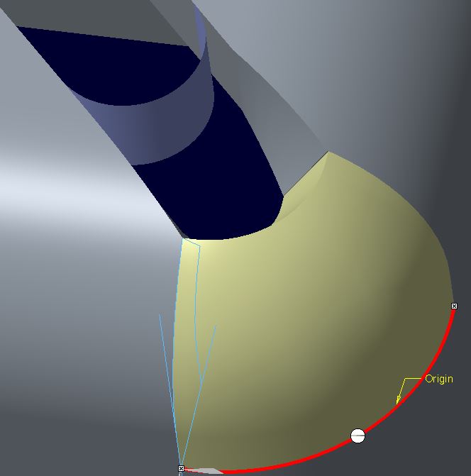
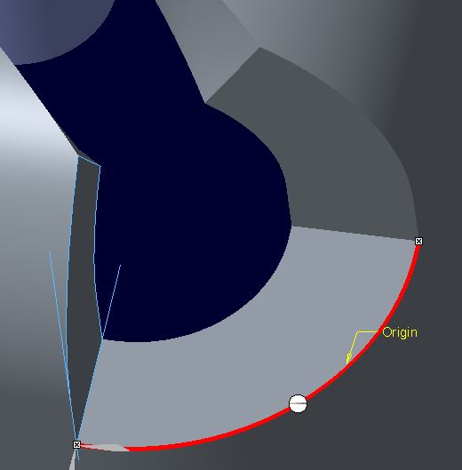
I have tried various ways in sheetmetal to fill the corner in and currently only a sweep fills in the corner, but only as a surface.  When choosing Solid (sweep as wall) sheetmetal is incapable of creating the geometry.  I am going to continue trying, but hoping someone has figured out how to do this?

Sheetmetal Corner.JPG  Sheetmetal Corner as Solid.JPG


This thread is inactive and closed by the PTC Community Management Team. If you would like to provide a reply and re-open this thread, please notify the moderator and reference the thread. You may also use "Start a topic" button to ask a new question. Please be sure to include what version of the PTC product you are using so another community member knowledgeable about your version may be able to assist.

5 replies

Pieface1-VisitorAuthor
1-Visitor
July 8, 2016

I went to Failed Geom and the following displays so I think I have a clue?

Sheetmetal Corner Failed Geom.JPG

23-Emerald III
July 8, 2016

This is something Creo sheetmetal can't handle. Creo sheetmetal only does straight, non-intersecting bends when it comes to bending and unbending.

The math for those bends is straightforward.

Once you get to intersecting bends, you get deformation that is not simple math. You would then need tooling (forms and dies) that gives you the desired shape.

17-Peridot
July 8, 2016

Creo doesn't do corners well.  And if you try to fix them, it doesn't do fold/unfold well.

So you have to pick your poison.  Do you want good geometry or do you need flat pattern capabilities.

Otherwise, you can always convert your part back to solid model and work with it at your content.

I only need flat pattern from time to time.

1-Visitor
July 8, 2016

please, see attached file for some idea.

Check deformation control tab in unbend feature

Creo 3.0 commercial

Pieface1-VisitorAuthor
1-Visitor
July 8, 2016

Thanks everyone for replying.  Thank you Darek for the model.  Funny to see how it treated the two right side corners.  I am where I am and still am going to attempt to solidify the corners and hope it will flatten

Yes Antonius I do need the flat pattern, not only the flat pattern but they want the stages of the processed part.  That is being done with bends/unbends using a family table.

23-Emerald III
July 8, 2016

We had a similar discussion not too long ago. Re: Creo Sheetmetal - Joggle Tangent Lines

There is a nice video of making a part very similar in one of the responses.

With regular press brakes, you really can't get to that part. The straight bends are easy and can be fully calculated by creo (if you have the right k or y values) but the deformed corners are gonna get you. It's a much more involved process than what creo can calculate. There is wrinkling and stretching and thining that creo can account for in the math.

1-Visitor
July 8, 2016

Attached file is the similar corner design with the cut and full round crossing the bend

Please, resume the unbend feature.

Edit: attached file corrected

Capture.JPG

3.JPG