1-Visitor
May 13, 2016
Solved

hole call out help

  • May 13, 2016
  • 6 replies
  • 31052 views

Greetings:

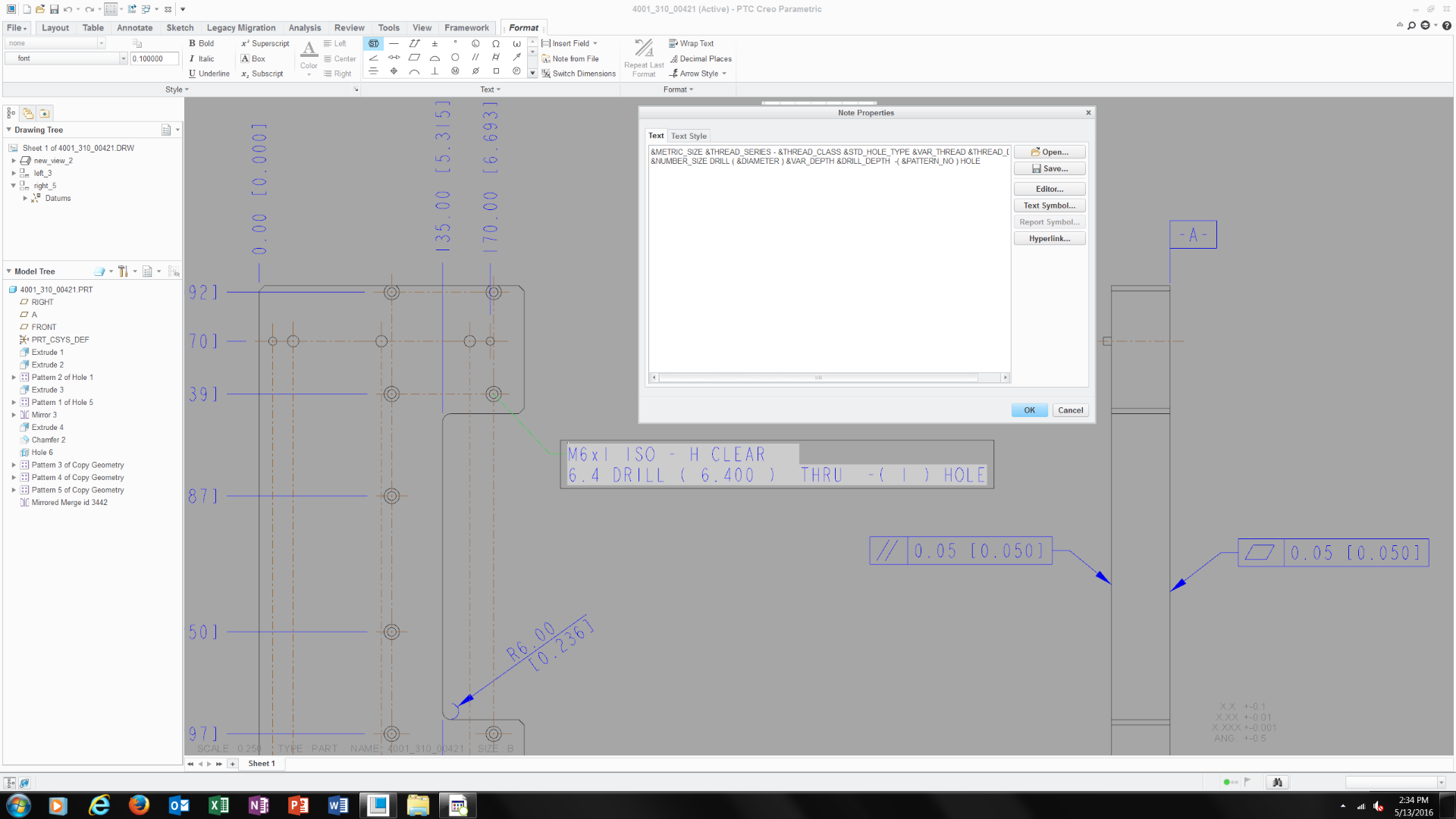
I'm really struggling to understand Creo's drawing module and one of the issues is hole callout.   I was told that the drawing mod.  does have that ability and you have to use 'Show Model Annotation"  weird but okay.  So I found out a how have hole call out show but the callout is not what I was expecting.   Need some help on this been at it for 1/2 cay and still can figure it out.


This thread is inactive and closed by the PTC Community Management Team. If you would like to provide a reply and re-open this thread, please notify the moderator and reference the thread. You may also use "Start a topic" button to ask a new question. Please be sure to include what version of the PTC product you are using so another community member knowledgeable about your version may be able to assist.
Best answer by cgorni

To close this community thread on Hole Callout Format


Summary of the exchanges and proposed solution, also summarized in article CS28399:

  • Default callout for Standard holes can be customized in the CALLOUT_FORMAT section of associated .hol file, located in the <Creo Installation>\Common Files\text\hole folder:
    • For example C:\Program Files\PTC\Creo 8.0.0.0\Common Files\text\hole
    • The configuration option hole_parameter_file_path can be used to set the location of custom .hol files
  • Under the CALLOUT_FORMAT section you can use different tokens that represent parameters or symbols, for example &DIAMETER that represents the Drill Diameter or <ctrl-a>v<ctrl-b> for the counterbore symbol
    • A list of tokens can be reviewed in the Creo Help Center, like here for Creo 8.0 (note that some parameters may not be applicable for previous releases).
  • This section will apply to all Hole types, so unwanted information displayed for some configurations:
    • If some tokens are not required when the Hole state changes (eg adding a Countersink or setting the Thread depth Through all) you can create a table in a new DEFAULT_CALLOUT_FORMAT_DATA section at the bottom of the hole chart file.
    • The different callouts can be defined for each combination.
    • Refer again to Creo Help center here for more details
  • Specific examples are discussed in the different replies oh this thread

6 replies

17-Peridot
May 14, 2016

PTC Creo Parametric uses a lot of lookup tables to come up with parameter names.  Some of these are managed internally which makes following a particular parameter (variable) hard to follow or use at will.

One of the lookup table sets are the hole tables.  They have the text version of the text that will show up in the dialog box for hole annotation.

Sometimes it is worth the time investment to make the tables do what you want.  For me, this isn't the case as I have many clients all wanting their own.  I simply create notes with the annotation I require for each client.  It is still associative if I build the note using available parameters.

Word of caution if you go changing Creo system level files... these are easily lost in a software update.  Either point your config.pro to a location outside the Creo folder structure or save the library to a backup location and remember to replace them when the updates occur.

1-Visitor
May 16, 2016

Is it this table?

24-Ruby III
May 16, 2016

Hi,

Hole definition files are text files with .hol extension in hole subdirectory.

In my installation it is C:\PTC\Creo2_M070\Creo 2.0\Common Files\M070\text\hole​ directory

MH

1-Visitor
May 15, 2016

‌The parameters used for the hole note are the columns found in hole tables. The hole note itself may include more parameters than what you want as the note is formated so that it displays the relavent parameters depending on whether you are defining an English or metric standard thread. Try looking up hole table parameters in the help, it lists the parameters for each thread type. The note itself is defined in the hole tables. For symbols, such as the depth symbol, you need to determine the ASCII code to be used.

3-Newcomer
May 15, 2016

I usually don't remember what's relavent either so I use control "x" to cut after maybe &STD_HOLE. Then check the drawing and go back and add part of what you cut if missing something and/or if good then just add the depth symbol with the "d" number for the depth dimension in the part. It gets me there, wish ptc made that easier in creo Also the next holes are easier once you get the hang of it.

1-Visitor
May 16, 2016

Attached is part of the default UNC table and the reference to the help documentation as to what parameters are used:

UNC Hole Table.JPG

Callout Format.JPG

You specify the parameters you want below the CALLOUT_FORMAT.

1-Visitor
May 16, 2016

Thank you.

I believe I'm pretty much in over my head on this. 

1-Visitor
May 16, 2016

It's very much like creating notes with displayed dimensions. I'd say first determine whether you are going edit the standard tables or create your own. If you create your own, make sure THREAD_SERIES in the header is set to what you want to appear in the thread specification drop-down of the hole feature, as this is what is shown, usually the same as the hole table file name.

Under CALLOUT_FORMAT add the parameters and other text and symbols you want to show, any column heading in the hole table file is valid. Try starting with 1 or 2 parameters such as:

&FASTENER_ID &THREAD

then try adding symbols:

<CTRL-a>x<CTRL-b> adds the depth symbol. Try different values to see what you get, I haven't found a list that shows what letter gives which symbol.

Also look up Formatting Thread Notes and there is a link to the valid parameters for use in the CALLOUT_FORMAT.

1-Visitor
May 17, 2016

Perhaps the question I should ask is does anyone have an ISO.hole file they can send me so I can figure out how to do this?  

thanks

Frank

1-Visitor
May 17, 2016

Try this and see if it works. Start out with a variable depth hole adding the countersink and counterbore individually to the hole. The hole note should display the thread call out as the default and when you add a countersink or counterbore it should add the appropriate information. After you see that work change the hole type in the hole feature to THRU_ALL, when you do that the only thing that should display is the thread call out. If you add the countersink or counterbore you should only see the thread call out displayed, save your file and close. Go to the *.hol file and edit the DRILLED_DEPTH value for the desired hole to THRU_ALL, save *.hol file and re-open Creo. Edit the definition of the hole, select the Note tab, and select Reset. If the sequence was done right you should see the correct information displayed.

1-Visitor
May 18, 2016

I'll look into this.  I think I've cost my employer too much trying to figure something simple as this out.

cgorni16-PearlAnswer
16-Pearl
November 16, 2021

To close this community thread on Hole Callout Format


Summary of the exchanges and proposed solution, also summarized in article CS28399:

  • Default callout for Standard holes can be customized in the CALLOUT_FORMAT section of associated .hol file, located in the <Creo Installation>\Common Files\text\hole folder:
    • For example C:\Program Files\PTC\Creo 8.0.0.0\Common Files\text\hole
    • The configuration option hole_parameter_file_path can be used to set the location of custom .hol files
  • Under the CALLOUT_FORMAT section you can use different tokens that represent parameters or symbols, for example &DIAMETER that represents the Drill Diameter or <ctrl-a>v<ctrl-b> for the counterbore symbol
    • A list of tokens can be reviewed in the Creo Help Center, like here for Creo 8.0 (note that some parameters may not be applicable for previous releases).
  • This section will apply to all Hole types, so unwanted information displayed for some configurations:
    • If some tokens are not required when the Hole state changes (eg adding a Countersink or setting the Thread depth Through all) you can create a table in a new DEFAULT_CALLOUT_FORMAT_DATA section at the bottom of the hole chart file.
    • The different callouts can be defined for each combination.
    • Refer again to Creo Help center here for more details
  • Specific examples are discussed in the different replies oh this thread