1-Visitor
May 28, 2013
Question

How to put constraint on threads...

  • May 28, 2013
  • 2 replies
  • 10527 views

Attached is tie rod dwg. I am trying to do a FEA on the tie rod but results was not what I wanted.

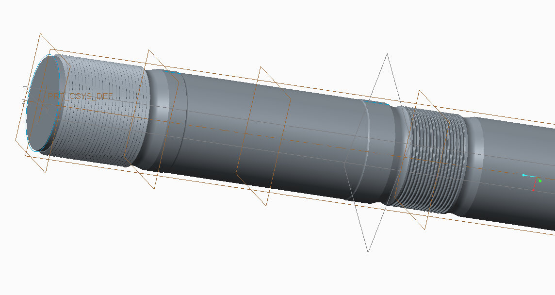
Anyway, I will start by explaning this tie rod. There are four tie rod that hold two platen in place. The picture shows half of a tie rod cuz I used a symmetric constraint on it. The is a platen in between the two threaded area and two nuts are holding this platen in place.

It has thread diameter of 9 1/2". So just using basic calculation with 825000 pre load on the tie rod. The stress should be around 12500 psi. But using FEA software (creo), the lowest stress I get by changing the constraint is 52000 psi. that's way too much for the material. I am wondering if I constraint it correctly.

Here is how i constraint it, I created a region where the nuts thread contact with the tie rod thread, I put the 825000 lb on this region on every thread.

Then on the opposite side of the thread (across from the above region, ie the slope part of the thread) I put a displacement constraint to constraint any movement on XYZ translation.

I am not sure if that's enough or can someone explain to me how to constraint a thread. Plus this part is relatively large so instead of drawing the actual thread, I drew it as a cut and revolve it then pattern it. I tried drawing the nuts in but the assembly would not mesh.

If someone who is can point me to a correct direction on how u would constraint this would be great. thanks in advance

tr.jpg


This thread is inactive and closed by the PTC Community Management Team. If you would like to provide a reply and re-open this thread, please notify the moderator and reference the thread. You may also use "Start a topic" button to ask a new question. Please be sure to include what version of the PTC product you are using so another community member knowledgeable about your version may be able to assist.

2 replies

13-Aquamarine
May 28, 2013

Hello Howard,

First, where are you wanting to calculate the stress? Are you expecting the rod to fail through the thread root? If not, there's probably no point trying to model the thread.

Assuming you do need to model the thread, I think your approach of modelling a simple revolve rather than a helix is a good one. I would go further with the symmetry, and use a 3.6° 'pie slice' of the rod - that way you're modelling 1/100th of the complete part, which makes dividing the load easy; and the model becomes small enough that you can use quite small elements in the critical region.

I'm not an expert in the mechanics of threaded joints, but my understanding is that the threads are not evenly loaded and that one or two may even be into yield. From this I'd say that you should really be trying to do a contact analysis with the nut, and that you should be using non-linear materials (available in WF5 and Creo 1 onwards, I think).

If you do want to try a simple linear analysis, then I'm not clear about your constraints but I would do it like this:

0019_001.png

Cut the rod off a couple of diameters (so 20" or so) away from the end of the thread detail, and constrain it on the end face. Then apply a pressure load to each loaded thread flank, and use Review Total Load to adjust the pressure value until you get 8250 lbf total force (1/100th, remember) along the axis. The load distribution won't be right and you may get a stress concentration at the edge of the loaded surface, but it'll be a start.

Don't forget the cyclic symmetry constraint, too.

Also, model the smallest section of the component that you can get away with. If both threads are loaded but one is larger than the other, just model the smaller thread and cut the rod off before the larger one

HTH!

1-Visitor
May 28, 2013

I basically load the way u sketch, I create a region where the nuts thread supposed to came into contact with the rod thread. But I put my constraint opposite of the surface of where u applied P. P=825000 lb

I am under the assumption that if I cut the thread in half along the Z-axis, the elongation would not be correct cuz I think symmetric constraint restraited the displacement.

The front few threads should have higher stress which is expected but not to the value of 55K psi as the material only have yield strength of 36K psi and ultimate tensile strength of 70K psi. The highest stress should be at the root of the thread which it is correct. I will try to attched a results in a few.

And using simple hand calculation Force/area, stress should be around 13000 psi.

13-Aquamarine
May 28, 2013

What do you get from Review Total Load? Could you post a screenshot of the Review Total Load window after calculation?

I'm not sure what your concern is about using a symmetry constraint, and I don't understand why you're applying both the load and constraint to the thread...

16-Pearl
May 28, 2013

What is it that you are trying to learn from the analysis? Do you need information on the thread root stress or are you looking for a way to pass the load into the shank/rod portion of your fastener? Either way, It is never recommended to conduct FEA on threads - it is widely recognized as a very difficult analysis to obtain even marginal results. “Handbook” calculations are often regarded as the best method to obtain root stresses. There is no symmetry in this type of part either. Of all the FEAs I've run in the past 20 years, I have run one thread simulation, under heavy protest with limited success, but only as a full contact model with its mating nut and using ANSYS with a highly refined mesh. The results provided the information we were looking for and the stresses were decent, but not as good as most any other type of analysis. Threaded fasteners are a highly non-linear beast, leading to the uneven, rapidly decreasing load sharing from the first thread onward. For an analysis of the rod itself, I would replace the threads with a cylindrical surface at the pitch diameter of the thread and apply the load at one end and a constraint at the other. Symmetry would easily come into play here to save a ton of solve time.

I hope this helps

1-Visitor
May 28, 2013

I need to prove that the highest stress at the tie rod is below the yield strength of the material (36K). Since the highest stress would be at the root of the thread, so I think I am looking for the root stress.

Can u show me where to get the "handbook" calculation? I am just using the total preload divided by the area of the root diameter. But isnt that mean every root thread have the same stress?

the thread is 9.5 major diamter, 3 tpi.

16-Pearl
May 29, 2013

Any good machine design reference will have methods to calculate root stress. More importantly, fasteners are typically designed to fail through the shank and not the threads. Many fastener manufacturers will provide a reference on the load limits of their fasteners. Your design appears to have a generous undercut which provides an ideal location to have the clapming system fail if overloaded. A simple F/A will do the job quite nicely for you if you evaluate this minimal cross-sectional area of your undercut.

There is a very good threaded fastener reference here:

http://www.bossard.com/en/Application-Engineering/Technical-Resources.aspx