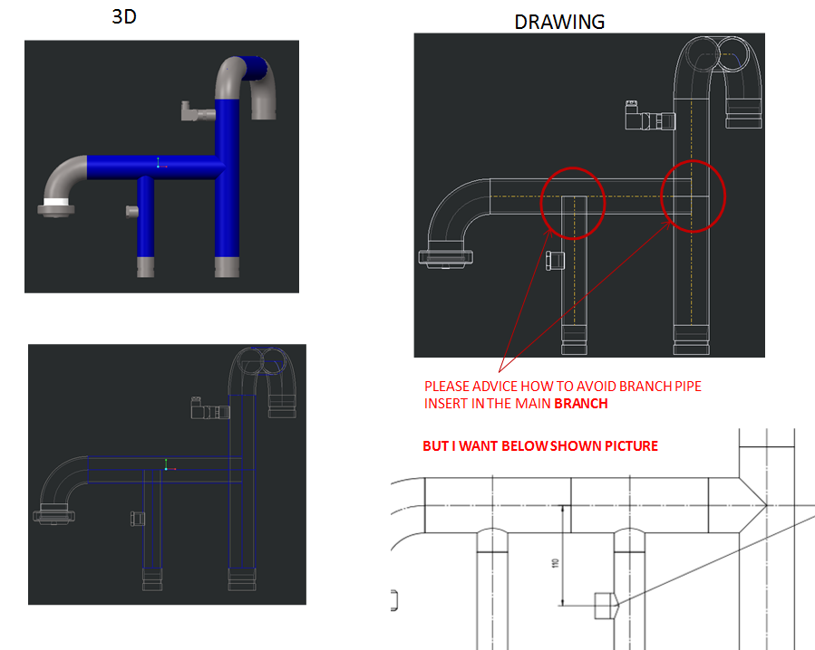
Hi you should probably look at how these would be manufactured. I doubt that a hole will be drilled in the side to create a branch and the end of the pipe scalloped out. It's far more likely that there will be branch tee fittings and clean normal cuts on the pipework. You should model up branch tees and add ports to allow them to be aligned properly.
Pulled tees and coped fittings are very common in piping. The same thing also applies when creating custom wyes, etc. I too am needing to figure out how to perform different end cuts on pipes.
Does anyone have any input? I can put cuts in my parts, or in the pipe assembly, but it seems like the Piping application should be able to do this. EFX does this for structural pieces, so why wouldn't piping?
Piping only will do a cross cut so all pipes/tubes are square cut at the end. Model up your fittings to create Tees, wyes, reducers etc. They should include the co-ordinates you need to make piping chop the pipe to the required lengths and a location point to position it accurately along the route. Hope that this helps, you can't just run two pipes together and hope it will work out the chopped geometry, i'm afraid.
Hopefully I have some big news here. I mentioned this thread to my counter part at another business unit, and he said his system copes the pipes. We are running off of the same settings, so we did some digging to figure out it. This might not be an all-inclusive solution, but we found a way to make it work every time for us, and ways that it does not work for us.
Just to tease the point, here are the ways it doesn't work first:
Using sketches to define both pipelines. There is no trimming done on the 2nd pipe or hole in the first.
Extruding first pipeline. Adding a datum point to it (offset from the end) to locate your second pipe, and then extruding from there. There is no trimming done on the 2nd pipe or hole in the first.
A VERY slight modification to either method is what we found works every time (for us). Create your first pipe in whatever means you find best. Doesn't matter if it is following a sketch, extruded, etc. Where you want your second pipe, Insert a straight break component (we used a tee). Doesn't matter what one, what the size is, or anything. Delete the fitting (notice it also deletes the pipe joint but leaves the datum point.) Use this datum point as the start point for your 2nd pipe.
Our only explanation is that the datum point is then associated with the pipe extrude, instead of just the pipe end, but this still seems crazy to me. Either way, it works!
Spec driven could also make the difference.
James, how are you creating your pipe segments? Would you mind testing it in one of the manors that I said didn't work (without using specs either) to see if we can replicate it?
I haven't tested creating pipes from sketches yet... but I DID see a very similar performance as you did when I added a pipe from a 2nd pipe extend (while using NON-spec-driven piping). Similarly, if I used the "pipe break" feature at all, it wouldn't seem to do what I wanted.... so I think your hypotheses could definitely be valid.
So, I think at the end of the day - it really comes down to creating "proper" branches. Spec-Driven Piping handles a lot of the branching for you automatically... so that may be why I haven't had a problem with it.
I'm finishing up preparations for LiveWorx the rest of this week (we're announcing/launching our Spec-Driven Piping configuration tool, as well as some really cool automation tools)... but I promise I'll try to test this more for you once I get back