1-Visitor
March 25, 2016
Question

Toroidal bend

  • March 25, 2016
  • 3 replies
  • 7235 views

Hello i went through a guide with torodial bend : Tutorial: How to model Tire in PTC Creo Parametric and show design intent - GrabCAD

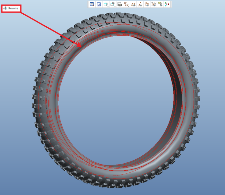
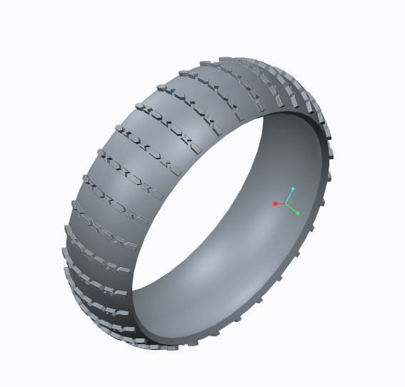
I did the basic part but what i wonder is how he does step 11 and build on (extend) the sides of the tire. I cant choose the side or anything what is best way to do? he says to the step 11 description that he used revolve cut etc, but should you instead before making the Bend have a wider part where the sides are not with pattern like this:

Picture 1-widetire

STEP 11 - HIS PART IS TO THE LEFT, MINE IS TO THE RIGHT

tire2.pngTire3.JPG

3 replies

13-Aquamarine
March 25, 2016

Hi Bjorn,

He's just saying you can add any other feature you wish at the end. It looks like he added another revolve to add in the extended sides. There are a few ways you can do similar things in Creo. You can also look at the Flatten-Quilt / Flatten-Quilt Deformation commands. This offers another potential method for achieving similar geometry.

Toroidal Bend is one of those rarely used niche functions in Creo. Some people make them to just to demonstrate their prowess but you rarely see anything created with them other than a tire. Literally, they may as well have just called it Tire Feature. However, flattening a quilt and then bending back solid geometry created from it can yield some pretty amazing results. I'd encourage you to give it a try!

Thanks,

-Brian

1-Visitor
March 27, 2016

Hello brian and thanks for the answer. okey but how did he use the revolve to extend the side? and make the revolved geometry be coincident with the tire geometry (as you cant select the side of the tire where his revolve extends)

Ok thanks, I will look it up

1-Visitor
March 13, 2017

Hi, everyone

Let's start with a simple example: I have a toroidal bent which becomes a bushing. In the 2D drawing I want to have the bushing and the unbent feature. How can I do that?

Thanks,

Nic.

21-Topaz II
March 15, 2017

What I usually do is build the model as the flat part first with features maybe like this:

- Main shape

- Holes and other added features

Then I define the toroidal bend.

I then define a family table, with entries that are called something like "part-bent" and "part-flat". I put the toroidal bend feature in a family table column, and make it "Y" for the bent one, "N" for the flat one.

On the drawing, you bring in the flat instance, define all the dimensions and stuff for it, then add the model for the bent one, and define views for it. You can have as many models as you want in a drawing. It just gets a bit tricky when you're setting view scales - you have to "set" the current model to set the scale for the views that show it.

1-Visitor
July 30, 2018

Hello there, do you guys know how to create Toroidal Bend with OVERLAPPING END??? Appreciate your help ASAP