1-Visitor
April 9, 2013
Question

Use whole wrapped sketch as trimming object on surface

  • April 9, 2013
  • 7 replies
  • 10066 views

Hi modellers!

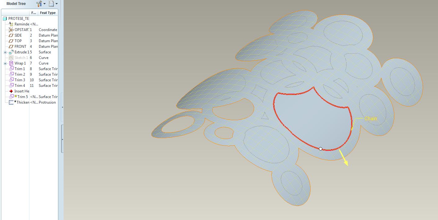
I have a sketch (imported from illustrator) that I've have wrapped onto a curved surface.

Now I want to use the wrapped sketch to trim the surface.

The problem is the fact that I'm only allowed to pick one outline for each trim. This means that I have to really many trims to get the surface I want.

Is there any way to do this proces more efficiently and speed up the proces?

I want all the centers of the circles cut out, like the three in the lower left corner.

wrap+trim.JPG

Best regards.

7 replies

17-Peridot
April 9, 2013

In some cases, you can project those curves back to flat plane sketch and then extrude that sketch to remove material. In your case, this would work easily as the curved surface is less than 90 degrees.

re-wrap.JPG

Patriot_1776
22-Sapphire II
April 9, 2013

Query-select the curve and see if it won't let you select the ENTIRE curve (composed of all of them). If not, as Nike says, Just do It.

17-Peridot
April 9, 2013

PTC isn't listening to Nike... You can only select a single closed loop in the trim tool. You get the option to select the Rule-based "All curves in feature" but it won't allow selection of a wrapped sketch with multiple closed loops.

On the other hand, you can extrude a thin feature and remove material, which, of course, has to be planar. I see room for improvement here

Patriot_1776
22-Sapphire II
April 9, 2013

Yeah, wasn't sure, I'd not come across that with the multiple loops. You'd THINK you could select the whole feature, but nooooooooo......

1-Visitor
April 10, 2013

Thank you for your answers both of you

I manage to solve the problem by projecting the wrap back to the sketch plane and extrude the holes away.

If you have a surface that bend more than 180 degrees, you have to do it the hard way?

Thanks again.

1-Visitor
April 10, 2013

You can also use Sheet Metal Module for this purpose.

answer2.jpganswer1.jpga2.jpga1.jpg

Patriot_1776
22-Sapphire II
April 10, 2013

Why not project it onto a flat surface, cut your quilt, do a spinal bend, and then thicken the surface?

17-Peridot
April 10, 2013

I was waiting for that one.


You have to be careful with spinal bend not to scale the part along the bend contour.


If the surface was not one that lends itself to a "wrap", it would be a great choice.

Patriot_1776
22-Sapphire II
April 10, 2013

Who, ME???

For the one he wanted, it seemed like it would work fairly well. It'd be interesting to do 2 on top of each other and see if there was any distortion.

I've found that the intersection of 2 curves is NOT exact in creo anymore, so if that curve is crucial, use a curve from the intersection of 2 surfaces. Dunno why there's the discrepancy now.......

Yeah, in Pro/E, there's a dozen ways to skin a cat (and sometimes you have to try ALL of them to find one that actually works...... ).....

1-Visitor
April 11, 2013

Actually the screenshot was of a simplified problem.

What I actually need, is to cut the holes in a double curved surface. I don't think that sheetmetal and spinal bend would help me here. Maybe? Otherwise it's a great way to do it.Thanks for the suggestions.

I manage to solve it by extruding the wrapped sketch that was projected back on a workplane... and because you can't wrap a sketch onto a double curved surface I had to create a single curved "dummy" surface that immitated the double curved surface as close as possible.

The result:

shell_test.jpg

It's still just a test and not the final part.

Thank you very much for your help. You just helped me gain some new CAD skills

17-Peridot
April 11, 2013

Indeed, that does become work. What is the manufacturing process for the part? Is it thermo-formed plastic or coined metal where it starts out flat when the holes are punched/cut?

You might try a sheetmetal part using a form-feature. That module can do some amazing things with adding holes on curved surfaces and managing deformation. I haven't found a way to unfold that as a metal part but you can lift a surface from it and flatten that to check what you start out with when you get the sheetmetal part done.

1-Visitor
April 11, 2013

All right. Will take a look at form-feature.

It's planned to be 3dprinted. The quantity is only 1 and it gives me alot more freedom regarding the geometry.

Patriot_1776
22-Sapphire II
April 11, 2013

I think what Antonius is getting at is how is it going to be manufactured in the real world? This will determine exactly how you'll need to model it to account for the method and any material stretching (as in sheetmetal or formed sheet plastic - I guarantee your holes will NOT be round). If it's going to be an injection molded plastic part, simply use a projected cut and draft the edges, because that's the way the mold will be made.

If this is just some fantasy part for fun and never being actually made, do you really need to wrap anything or are you just doing it for fun? Hell, simply extrude the holes thru it normal to the back plane and be done with it unless you need or want anything else.

I'm thinking of a method you might be able to use for a wrap on a compound-curved surface, but it'll most likely require a couple steps.

Patriot_1776
22-Sapphire II
April 11, 2013

Just for fun, I wrapped a series of circles onto a "developable" surface thas has curvature normal to the exis of the final part. So, the circumference of the circles is correct (unlike projected). then I did a spinal bend on it to get the compound curvature (like a revolved surface). As you can see, now the holes are distorted near the top (smaller end) where the spinal bend actually shrunk the material. I wrote a relation to force the developed length to be equal to the big end. I could easily have donw it the other way with the relations to make the holes near the top undistorted and have the material stretch (as would more normally be the case) to distort the bottom. But, this was quick and easy. Note: This is sort of cheating to create a Toroidial bend, with greater flexibility. I later thickened it and it worked at 1" thick no problem!

COMPOUND-CURVE_WRAP-01.JPG

For you though, what I'd suggest is simply punching holes thru a surface, normal to a point on the surface corresponding to where the axis of the hole goes thru, then thickening the surface. This will give you distortion of the walls of the holes, based on the thickness. This will most likely give you geometry most closely matched to a real world production process.

1-Visitor
April 12, 2013

: 3dprint is going to be used as the manufacturing process in the real world. With the rather complex geometri (a lot of details will be added to the surface) that I need to be as precise as possible, and the fact that I only need one single piece, I think 3dprint is going to be the most suitable manufactoring proces.


I need to wrap it as much as possible, because I don't want the pattern to be stretched. The pattern is probably going to be more complex and not just simple circles. It was just for testing.


Unfortunatly I don't think I can use the spinal bend method as I need the double curved surface to be quite precise. I think it's easier to get an excact shape with a boundary blend tool compared to a spinal bend.


@Antonius: All right. I also think I got what I needed.


Again, both of you, thank you for your help. It's much appreciated.

Patriot_1776
22-Sapphire II
April 12, 2013

Well, it looks like you got it then. The pic looks good.