1-Visitor
April 18, 2014
Solved

Mapped Mesh on Fillet

  • April 18, 2014
  • 3 replies
  • 10170 views

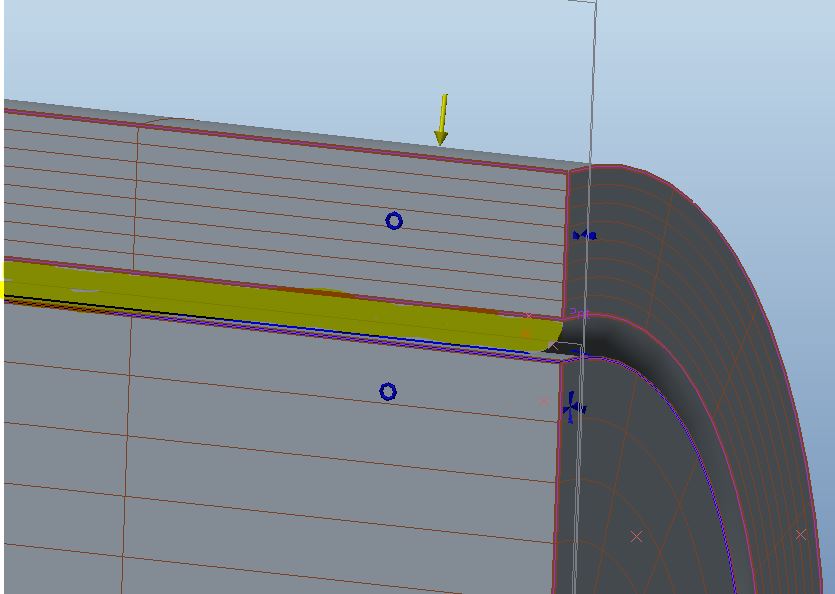
I was wondering if anyone can tell me how to create a mapped mesh on the geometry highlighted in yellow. I used to have just a cylinder with no fillets. I used brick elements on the oter tube and wedge elements on the inner cylinder. This ran nicely. This is a hyper-elastic/contact analysis. Now I added fillets and I have no idea how to create wedge elements in the radius portion. I was thinking wedge elements in the radius portion and brick in the rest. Can anyone help?

mappedmesh.JPG


This thread is inactive and closed by the PTC Community Management Team. If you would like to provide a reply and re-open this thread, please notify the moderator and reference the thread. You may also use "Start a topic" button to ask a new question. Please be sure to include what version of the PTC product you are using so another community member knowledgeable about your version may be able to assist.
Best answer by sdensberger

Paul and Charles,

I was able to create a mapped mesh of the geometry (or atleast on a piece of geometry I created to match yours); you can view the pdf here. This was done entirely in integrated mode.

That being said, the mapped meshing feature in Simulate is rather frustrating at times (to say the least).

3 replies

18-Opal
April 18, 2014

Hi Paul,

I have reviewed the image of your model. Your assumption is correct....for the fillet region you should be creating a WEDGE mesh.

The available selection types for creating mesh regions are datum point, vertex, edge and 3 sided surfaces (4 sided in case of BRICKS).

In the event that such references do not exist, you can always select surface/edge locations.

The mesh region points are connected along common edge.

Note: If edge does not exist, then common surface is tried and joined along it. If both of them do not exist, the points are joined via straight line.

Would you be able to share your model? I would like to give this a try.

Hope this information helps.


Regards,

Mark

1-Visitor
April 18, 2014

I need to see if it is ok to upload my clients model (which I think is doubtful). In the meantime. If you created a tube with an OD of .362" and an ID of .263" then added a .010" radius to the id on either end this would be representative of the outer piece. The inner piece is just a cylinder with a diameter of .260". Both outer and inner are 1.0" long. The assembly would just be the both pieces together as shown in the above image. I am simplifying the geometry here but this will show the problem I am having. I just don't know quite how to make the selection for the wedge elements on the radius portion. Then beyond that, I am hoping to fill the rest with bricks....

1-Visitor
April 18, 2014

Oh....I forgot. I cut the assembly in half so I could apply a symmetry constraint.....

2-Explorer
April 24, 2014

Paul and Charles,

I was able to create a mapped mesh of the geometry (or atleast on a piece of geometry I created to match yours); you can view the pdf here. This was done entirely in integrated mode.

That being said, the mapped meshing feature in Simulate is rather frustrating at times (to say the least).

13-Aquamarine
April 24, 2014

Shaun,

That certainly answers Paul's question,

I used your method and then with 90 deg volume regions (which effectively gives the same vertices to pick). Keeping the subtended angle of any mapped region <=90deg seems key if 'self intersecting' error is to be avoided.

Using only a 10deg portion of cylinder I expected to be able to get the vertex selection method to work (using field points to find the internal corner of the wedge). I could not and got errors : 'self intersecting' and 'mesh region is not fully contained in the model' and 'included angle between the edges is out of range' depending on what order I did things.

The point about the old Rasna 'revolve' delete shells (y/n) was that is was really really simple and intuituve.

Successsful Mapped meshing tactics are just not obvious (if possible) and will put users off the functionality.

15-Moonstone
April 25, 2014

Hello, Charles,

It's just a story, as you have referred to Rasna, for those who would not have known, even under DOS.

Cordially.

Denis.

18-Opal
May 1, 2014

Hi Paul,

I was digging into the issue related to keeping the subtended angle of any mapped region <=90deg to avoid the 'self intersecting' error with the Simulate development team yesterday.

Technically, we support the angle of mapped regions to 180 degreed. Would you please open a ticket with technical support and raise this issue? While I know you may not be able to provide the actual model, I ask you to submit your test model.

This way, we will address the issue and have it linked directly to you.

Regards,

Mark