1-Visitor
March 6, 2017

MBD: Standalone Annotations vs. Annotation Features

  • March 6, 2017
  • 34 replies
  • 19343 views

In Creo 4.0 one of the significant enhancements was to provide advanced capabilities for standalone annotations of the following types: Geometric Tolerance (GTOL), Datum Feature Symbol, Datum Target and Dimension. In this blog post, I'll provide a little bit of background to explain the differences (up through Creo 3.0) between standalone annotations and annotation elements owned by an annotation feature. Then I'll explain in more detail the enhancements in Creo 4.0 and I'll finish up with some advice on when you might want to consider using either standalone annotations or annotation elements owned by annotation features.

What is a standalone annotation and how is it different from an annotation element inside an annotation feature?

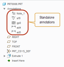
A standalone annotation is an annotation that is not "owned" by some other feature in the model. These annotations are listed in the model tree under the Annotations node.

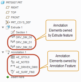
Annotation elements, by contrast, are owned by another feature in the model. Typically this feature is an annotation feature, but it can also be general modeling feature (such as Extrude or Hole).

Generally speaking, standalone annotations have the same graphical appearance and the same basic properties as annotation elements. For example, the dialog box for configuring a GTOL is identical whether that GTOL is a standalone annotation or an annotation element.

What sets standalone annotations apart from annotation elements are a number of advanced capabilities that annotation elements have as a result of being part of an explicit feature in the model. Those advanced capabilities are:

  • Reference handling and regeneration
    • Annotation elements can support multiple references of various types (to support the semantic definition of the annotation) and they regenerate at a specific point in the regeneration sequence determined by their owning feature. If something goes wrong during regeneration, annotation elements will provide either a failure or a warning in the Notification Center and the model tree.
  • Support for parameters
    • Annotation elements can have parameters and some types have a number of system parameters that get automatically created for the various properties of the annotation element.
  • Ability to Designate and mark as Control Characteristic
    • Annotation elements may be designated and made visible to Windchill and also identified as a control characteristic and have a Windchill model item that gets passed to MPMLink.
  • Support for feature operations
    • The annotation feature, which owns the annotation elements, may participate in feature operations, such as pattern, suppress, copy, etc...

For companies moving to Model-Based Definition, these advanced capabilities make annotation elements within annotation features the preferred choice in Creo 3.0 and earlier.

Enhancements to standalone annotations in Creo 4.0

In Creo 4.0 we have enhanced the standalone annotations for GTOL, Datum Feature Symbol, Datum Target and Dimension to include most of the same advanced capabilities that were previously only available for annotation elements inside annotation features. So, these types of annotations will now support:

  • Reference handling and regeneration
    • The contextual ribbon tab for the enhanced standalone annotations will have a References button available at the far left side of the ribbon where you can select the references that you would like to have as the semantic definition of that annotation
  • Parameters
    • You can access the parameters of the enhanced standalone annotations from the right mouse button menu
  • Designation as Control Characteristic
    • You can access the options to designate and set control characteristic from the Options button in the contextual ribbon tab for the enhanced standalone annotations

The only capability not available to standalone annotations is the ability to support feature operations, which will still only be possible when annotation feature is used.

It is important to note that these advanced capabilities are only available in Creo 4.0 for the standalone annotations of the four types noted above. Other types of standalone annotations (such as Notes, Symbols, Surface Finish Symbols) do NOT have these advanced capabilities and the standalone annotations of these types will behave as they currently do in Creo 3.0. We plan to provide the advanced capabilities for these remaining annotation types in Creo 5.0.

When to use standalone annotations or annotation features in Creo 4.0

Given that most of the advanced capabilities of annotation elements will be available with standalone annotations (for GTOL, Datum Feature Symbol, Datum Target and Dimension), there is less of a need to use annotation features in Creo 4.0. Here are some criteria that can help you decide which method to use.

Reasons to use annotation elements and annotation features:

  1. If you are using an annotation type that has not been enhanced in Creo 4.0
    • Remember, the only annotation types that were enhanced are GTOL, Datum Feature Symbol, Datum Target and Dimension, so if you're using symbols, notes, surface finish, etc... you'll still likely want to use annotation features for these
  2. If you want to perform some kind of feature operation on the annotations
    • Standalone annotations are not contained inside an explicit feature in the model tree, so you cannot include them in feature operations, such as pattern, copy, suppress, UDF, etc... If you intend to do some kind of feature operation, then you'll still want to use annotation features
  3. If you want to organize your model tree using annotation features
    • Standalone annotations appear in the model tree under the Annotations node at the top. They are presented in a flat list grouped by type. If the model contains a large number of annotations, it might become a little hard to manage such a long list of annotations in Creo 4.0. Using annotation features would allow you to group and structure the annotations in the tree.

Besides the three reasons above there generally aren't any other advantages to using annotation elements over the enhanced standalone annotations. Most importantly, you can capture the full semantic definition while using the enhanced standalone annotations and it is this ability to define fully semantic GD&T that many companies are considering the major benefit to a Model-Based Definition.

If you have any questions, please let me know in the comments below.

-Raphael

UPDATE: 2017-03-06

Moved this blog from Creo Sneak Peek group to the Model Based Enterprise group.

Also edited slightly to reflect the fact that Creo 4.0 is now shipping

    34 replies

    1-Visitor
    March 3, 2017

    Hi Raphael-

    Question.....

    Is it possible to add a driving dimension (technically, considered an AE) to an AF, in order to and have better control of which surfaces are included in that dimension, and are highlighted when that dimension is selected?

    The backstory......

    I was doing some comparing of model driven dimensions vs. added dimensions (Annotation Elements within an AF)  yesterday. The part I am defining has many cavities and steps, and it's a little difficult to see what the height dimension applies to when the entire model highlights if that model dimension is selected. Sure, the first feature was originally a nice block, but now the part  has so many different heights that it's really not clear which surfaces that height dimension (11)  applies to, unless you are looking at a straight on (2D!) view:

    driving_dim-straight-on.JPG

    Knowing how 2D views are frowned upon in MBD, I rotated the view and selected the driving dimension to see how clear this really is to the viewer, but the entire part highlights when you select the dimension, since this dimension is the overall height of the first extrusion:

    driving_dim-3d.JPG

    With an added dimension (AE), since you explicitly select two surfaces, only the surfaces at that distance  highlight when the dimension is selected, which makes it much clearer for the viewer:

    added_dim-3D.JPG

    The one caveat was that all surfaces on the plane highlighted, and sometimes there are surfaces on a common plane for which a tighter tolerance should be held on only one of those surfaces, so highlighting all the surfaces on that plane can be misleading and costly. I was trying to figure out how to add the model dimension to an AF, in hopes that I could better control which surfaces are associated to that dimension, but wasn't able to select driving dimensions (even though they are Annotation Elements).

    So, to re-state my question....if driving (model) dimensions are considered Annotation Elements, can I add them to the AF such that I can have better communication with the viewer? I am using CREO 3.0, M110.

    Thanks for any input!

    1-Visitor
    March 3, 2017

    Debbie,

    The short answer is, "No".

    Driving Dimensions are not Annotation Elements: driving dimensions are driving dimensions. A Driving Dimension Annotation Element is an associative, dependent copy of a driving dimension. Why create a copy of a driving dimension? Driving dimensions, in the 3D environment, are visible only when the feature to which the driving dimension belongs is being edited or redefined. An Annotation Element can, if desired, be visible at any time, even when a feature is not being edited or redefined: annotations are for the purposes of communicating information about a design/model, whereas driving dimensions are the means of controlling the size, shape and position of elements of a design/model.

    Driving Dimension Annotation Elements have a variety of functional limitations. One of their limitations is that they use the same references as the original driving dimension of which it is a copy. For example, if you have a pattern of identical holes, all of the same size, it is not possible to have a Driving Dimension Annotation Element that references all of the identical holes. Instead, when you select the Driving Dimension Annotation Element, only the one edge or surface of the one hole that contains the driving dimension will highlight. Similarly, in the situation you describe, you cannot change the references used by the Annotation Element that is a copy of the driving dimension: the copied Annotation only uses the same references as the driving dimension of which it is a copy.

    Another limitation of Driving Dimension Annotation Elements is that they cannot be included in Annotation Features: two different sets of functionality with very different behaviors and interfaces.

    Driving Dimension Annotation Elements are of sufficiently limited functionality that, but for the simplest of models, It's my recommendation that they not be used. This goes against 30 years of "conventional" wisdom of always using "shown" dimensions on drawings.

    1-Visitor
    March 3, 2017

    Thanks for your response, Charles.

    That's interesting that you refer to the AE version as a copy of the driving model dimension, as they are still 2-way parametric. I still prefer to use them, for that functionality, and also to ensure best practice of functional model definition in general. Yes, I know, I'm in  the minority on that.....

    But, I do see your point about the limited functionality, and see why they are limiting in many ways. In the hole example, instead of having the surfaces highlight, I would still use the drafting standard method, where the dimension itself calls out the number of holes at that size (2X holesize). I had a case where a part was family tabled, and the number of features in a hole pattern varied between part instances, and the note kept up with that information when I made the note reference the number of occurrences in the pattern.

    I see pros and cons to everything, and am  just trying to understand the most robust way to forge ahead into MBD without losing the wisdom of conventional practices, especially for those viewers and especially our vendors, who may still prefer a hard copy with 2D-straight on views. It's not only hard on us experienced users who are used to functional, model driven information, it's a gradual re-training  of our "audience". It'll be interesting to see how things are a few years from now.

    1-Visitor
    March 3, 2017

    That's a great explanation, Charles, the only comment that I would make is that I prefer to say that the DDAE (Driving Dimension Annotation Element) acts more like a "wrapper" on top of the underlying feature dimension rather than calling it a "copy". There is still only the one dimension in the database, it's just that it carries some additional cosmetic attributes once it is converted to DDAE.

    Everything else you said is spot-on!

    1-Visitor
    March 3, 2017

    Debbie,

    Everything that's been said so far is correct - for Creo 3.0 and earlier...

    In Creo 4.0 we now offer the capability to manually add semantic references for Driving Dimension Annotation Elements (DDAE).

    When you select the dimension, the Dimension ribbon appears and on the left side there is a button called References

    If you click on that button, a References dialog will open where you can add the surfaces you want to be the semantic references:

    There is an issue with F000 where it seems these surfaces aren't highlighting when the dimension is selected, but the references are there nonetheless and will be passed on to any downstream software that wants to use the semantic references. We will be fixing the highlight issue in an upcoming MOR.

    1-Visitor
    March 3, 2017

    You can also find a video and description of this enhancement in the PTC Creo Help Center:

    Creo Parametric Help Center

    There is a whole section on What's New in Creo 4.0

    1-Visitor
    March 3, 2017

    Good to know- thanks for sharing. I guess I don't need to totally abandon the use of Model /Driving Dims, then......time will tell, I suppose.

    1-Visitor
    March 16, 2017

    Hi Raphael,

    Another short question regarding MBD, if the aim is to clearly abandon drawing creation and move the definition of a component from the 2d drawing to 3d part with annotations. There is still to this date a problem when defining tables in the 3d.

    Ok we can retrieve any part/feature parameter in a 3d table by using the syntaxe "&name_of_parameter". But if i understand right, not all parameters available in drawings repeat regions are always available as assembly/part selectable parameters.

    At one point, it is planned in future to make all these repeat regions parameters available for selection so we can include them in 3d tables? or maybe add repeat region themselves as features in 3d mode?

    Thanks in advance for you help.

    1-Visitor
    March 16, 2017

    We do have a roadmap for offering tables as a 3D annotation. Whether these tables will support repeat regions as in 2D today is not decided. At a minimum, we would like to provide simple tables where you can enter text or add callouts to parameters.

    We're exploring some options of providing the information normally included in repeat region tables, but perhaps presenting it differently than as a table in the graphics window along with the model geometry. It's too soon to say right now what exactly that would look like, but we're working on it.

    1-Visitor
    March 16, 2017

    Im sorry when i write "3d table" i mean by that a 3d symbol looking like a table and containing parameters with syntaxe "&name_of_parameter".

    Ok thanks for the explanations and quick feedback.