1-Visitor
August 29, 2012
Solved

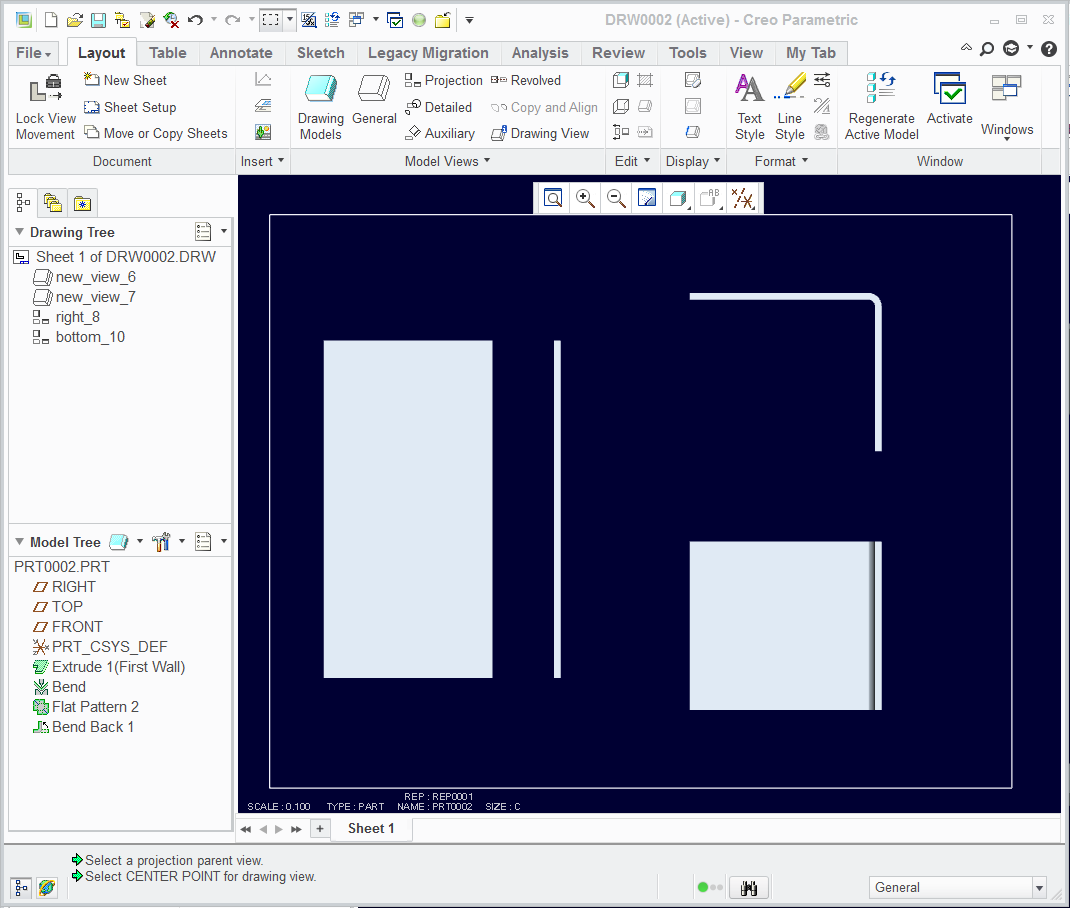
Flat pattern sheet metal drawing

  • August 29, 2012
  • 7 replies
  • 47670 views

Hello,


When creating a drawing of a sheet metal part, we currently use the family table method to have two models in one sheet. We would prefer not to use this method as it introduces an extra part number that we must track. We have tried using simplified reps however, this means all parent assemblies must have a simplified rep as well!


Does anyone have an alternative to using family tables that will allow us to put a flat pattern view into a drawing without using simplified reps? Either that or being able to change the master rep to exclude a feature.


Any help would be grateful.


Regards,

Hannah


P.S We are using Creo Parametric 1.0


This thread is inactive and closed by the PTC Community Management Team. If you would like to provide a reply and re-open this thread, please notify the moderator and reference the thread. You may also use "Start a topic" button to ask a new question. Please be sure to include what version of the PTC product you are using so another community member knowledgeable about your version may be able to assist.
Best answer by TomD.inPDX

I worked with it some more.

It really is a lesson in how the Display States works along with Simplified Reps (I didn't realize they were dependent). Always good to learn something new.

In short, I was able to flatten and then bend back the flange. Using proper technique in Excluding features will get you the Display States you need for the drawing -and- have the default be the master you want. It does cause features to fail regeneration but once they too are excluded from the simplified rep, these do not cause overall regen failures. The requirement you are looking for also comes with the price of thoughtful tree management and associativity. Nothing new, of course.

I think I've also run into a few bugs along the way, like the drawing views not following the default drawing scale. But that's another thread.

DisplayState3.PNG

7 replies

1-Visitor
August 30, 2012

Here is a movie I created for the purpose. It was created in WF5. Could be similar in Creo 1.0. With this method, the flat state is Automatically created in the family table. Further, it is always the LAST feature. Meaning any feature added after creation of Flat state would be put before the flat state by the software.

Video Link : 3236

hkenyon1-VisitorAuthor
1-Visitor
August 30, 2012

Thank you for the response, unfortunately, Creo does not have the same menus. I am also trying to avoid family tables for sheet metal as it would require a separate part. We would like one part number/name for the drawing and the sheet metal component. From this single part we would like to be able to place two different drawing views - flat and assembled. As stated above, we were unsuccessful using simplified reps and are trying to find a better option.

17-Peridot
August 30, 2012

You are looking for Combined States.

It is a bit convoluted but I believe this was added for the very reason you are looking for.

Here is a simple metal part showing it in a bent state and unbent state.

DisplayState1.PNG

DisplayState2.PNG

The idea is that you create a new view state as seen on the model lower graphics edge. Bent/Unbent/Default

While in that state, you can edit the visibility of a feature in the tree

In the drawing, when inserting a general view, it asks which Combined State you wish to use.

This is Creo 2.0. Let me know if you want the files.

hkenyon1-VisitorAuthor
1-Visitor
August 31, 2012

Hi Antonius,

Thanks for your response! It seems like this method is similar to creating simplified reps, and will cause a problem when assembling a sheet metal part. As the default view is to have all features included, it would mean that when you add a sheet metal part to an assembly, it will be the flat pattern. As the majority of our sheet metal parts are used in larger assemblies, this method would not resolve the issue we are having.

Is there a way to view the flat pattern without creating a feature? There is the flat pattern previewer however, you cannot do anything with this preview view...

Regards,

Hannah

17-Peridot
August 31, 2012

I worked with it some more.

It really is a lesson in how the Display States works along with Simplified Reps (I didn't realize they were dependent). Always good to learn something new.

In short, I was able to flatten and then bend back the flange. Using proper technique in Excluding features will get you the Display States you need for the drawing -and- have the default be the master you want. It does cause features to fail regeneration but once they too are excluded from the simplified rep, these do not cause overall regen failures. The requirement you are looking for also comes with the price of thoughtful tree management and associativity. Nothing new, of course.

I think I've also run into a few bugs along the way, like the drawing views not following the default drawing scale. But that's another thread.

DisplayState3.PNG

12-Amethyst
September 24, 2013

l´m really sorry, but don´t understand yours replies Andrew Hermanson and Antonius Dirriwachter. Could you make a screenshot/picture what do you exactly mean?

If l use BEND BACK it´s everytime push above flat pattern and regeneration of bend back is failed... it´s logicaly...but try to describe what do you mean with your previous replies. Thanks you in advice...

bend_back-flat_pattern.JPG

17-Peridot
September 24, 2013

I understand the problem you are having. I am not sure how I achieved the bend back after the flat pattern in the previous example. I will see if I can replicate the process and I will post.

I did look further into what I did for the dual states on the drawing. I did not use family tables but did use view states.

I will further investigate this and document it so that others can use the information. Please give me a few days to get this resolved to a satisfactory state. I will update this post if I find anything relevant in the meantime.

17-Peridot
September 24, 2013

I just confirmed it -can- be done but it doesn't make sense why; and it could well be unstable in case one tries to make changes. But: I used a simplified rep state to create the bend back while the flat pattern was excluded. Of course it failed because there was nothing to bend back. I next excluded the bend back from the new rep as well and regen allowed it. Saved the rep and went back to the master and the bend back remained below the flat pattern.

bendback.PNG

I then removed the added simplified rep; saved; erased all displayed; and reopened. No issues, no errors on regen. PTC really needs to take a look at this.

I need to think through how to best use this <snip> workaround.

Again, form features is a different challenge but we can also flatten forms with reps or family tables.

1-Visitor
December 19, 2013

Can someone tell me how to bend unbend pipe in Sheetmetel.

17-Peridot
December 19, 2013

Tubing is not sheetmetal. You cannot use sheetmetal to bend or unbend tubing.

14-Alexandrite
May 19, 2015

hello Guys,

I create this idea, and looks like this topic:

to have a default simplified rep in sheetmetal part (like assembly mode)

what do you think about it?

I already try the Antonio best practice, but I cannot reproduce it because the flat pattern still be my last feature.

Ron

July 17, 2015

Hi Hannah

Sheetmetalwork unbends always have a flat associated produced via family table.

You can arrange it so that the flat is inside the instance of the original family table, thus the unbend is the only extra operation and updates as its parent is edited.

In the drawing you can override the number_flat to make it read as the same part in the boarder field.

EG:

If you have the field in the boarder that is drawing_name:159 for the main drawing

and drawing_name:500 for the flat

You can right click on the field of the flat and over-write "drawing_name:500" with drawing_name:159.

This is something I do constantly.

If this is of any help, you are welcome

Francis