

Question
How to create bend lines or bend axis of a flatten hopper?
Dear all,
I'm a Creo 2.0 M100 user, in my company we use to offen manufacture steel hoppers (like the example in the attached picture). These hoppers are not calendered but made by traditional bending machines, so would be appreciable for the workers to receive a laser cutted sheet metal with alredy traced bend lines on it.
Is there a method to achieve this result?
Thanks in advance
Regards
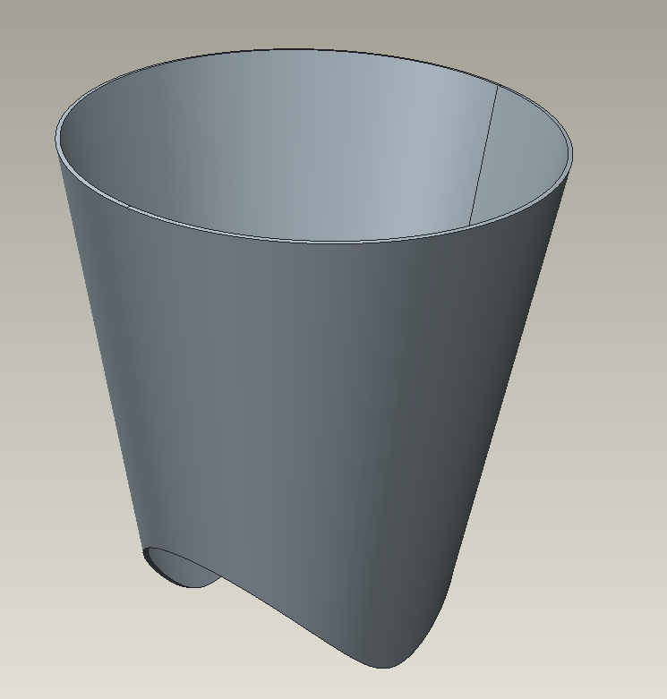
Sample hopper
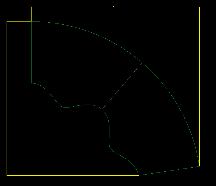
develop on drawing, without bend lines by default
This thread is inactive and closed by the PTC Community Management Team. If you would like to provide a reply and re-open this thread, please notify the moderator and reference the thread. You may also use "Start a topic" button to ask a new question. Please be sure to include what version of the PTC product you are using so another community member knowledgeable about your version may be able to assist.