1-Visitor
March 12, 2016
Question

sweep

  • March 12, 2016
  • 6 replies
  • 12968 views

Hi I have a small problem using a sweep feature in Creo 3.0.

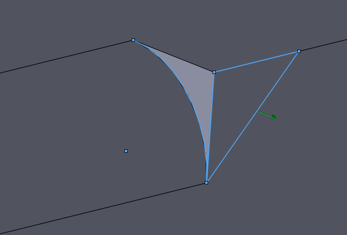
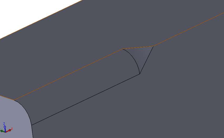
Using this sweep feature i can create sketch on a normal plane to trajectory line.

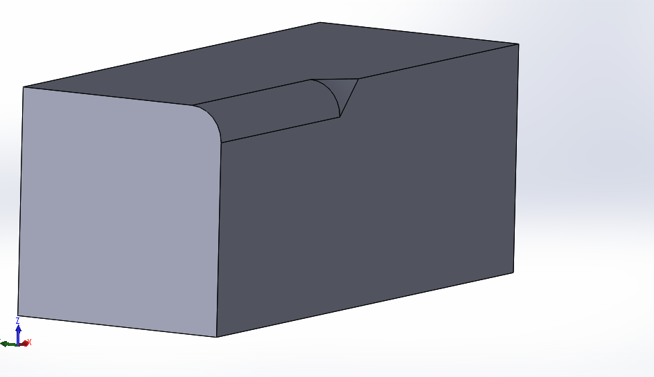
for example i am sending some screens what i want to do (this example i have made in solidworks)

p.s. sorry for bad englisch:p

1.PNG2.PNG3.PNG.


This thread is inactive and closed by the PTC Community Management Team. If you would like to provide a reply and re-open this thread, please notify the moderator and reference the thread. You may also use "Start a topic" button to ask a new question. Please be sure to include what version of the PTC product you are using so another community member knowledgeable about your version may be able to assist.

6 replies

kdirth
21-Topaz I
21-Topaz I
March 14, 2016

Use the variable section sweep option.  When defining the sketch create a relation for dimensions in the sketch (the variable "trajpar" is the trajectory from 0 to 1).

Here is a 100 mm round sweep cut followed by a shorter sweep with the relation "sd3=100-(trajpar*100)" (sd3 being the radius dimension).  A carefully created relation could do it all in one feature.

sweep.JPG

There is always more to learn.
17-Peridot
March 15, 2016

I do not see the sweep feature clearly on the SW version.  If you attach the SW file, I can see what it is doing and do the same with Creo for you.

abia?ow?s1-VisitorAuthor
1-Visitor
March 15, 2016

Ok. I'll do it later today

12-Amethyst
March 15, 2016

You can do this with a curve and the round feature. Create a sketched curved along one of the faces you want your curve, straight line the 3 point tangent or what shape you require. Create a round thru a curve, select the curve first, then select References and select the edge the curve will pass thru, and your done.round 1.JPGround 2.JPG

Patriot_1776
22-Sapphire II
March 15, 2016

As always, it depends on the actual SHAPE you want.  You could try a VSS using a curve on a plane thru the edge, at half the included angle to control the radius going from a value to zero.  that way you can use an "S" shape at the end to make that last transition tangent to the radius dimension, to tangent to the edge.

17-Peridot
March 16, 2016

The shape he is duplicating is very specific.  For Creo, it might as well be one of those "3D shape sweeps".  Look carefully at what SW is doing.

17-Peridot
March 16, 2016

This video is what I ended up using boundary blend along a series of ribs.  I could not get sweep to provide an alternate sketch plane in the required orientation.

In this case I used pattern along a spine with a redefined origin.  This ensures there is no offset due to some origin conflict which you cannot resolve using an axis pattern.

I do trust that this geometry is the same as it was in SW.  ...remember to set the video to HD.

21-Topaz II
March 16, 2016

Looking at the SW model, I know it's a sweep feature type, but it's essentially a revolve but the revolved sketch is on a plane that does not pass through the revolve axis.

Creo doesn't have the capability to either revolve or sweep in that manner, at least that I know of.  However, if you sweep along the fillet, you can get the same result.  You need 2 trajectories, a straight line through the center of the fillet (your normal and origin) and the angled line on the side of the rectangle. Your section is an arc with the center on the origin and one end at the other trajectory.

sweep.JPG

I've attached my Creo 3 model that should match the SW.

17-Peridot
March 16, 2016

This is what Rohit did and it is different.

We can easily "twist" a boundary blend.  Playing with it yesterday pretty much had me convinced that this was PTC's intent for this type of feature.

However, PTC is really falling behind by not exploring some level of 3D sketching and manipulation.  I know we will never see it in core Creo, but SolidWorks has a huge advantage here.

21-Topaz II
March 16, 2016

Looking at the screenshot Rohit posted, it doesn't look the same.  He's using 3 chains, I'm using 2.  His origin & normal curve is the edge of the solid, mine's the center of the fillet.

I'm pretty confident that this very closely matches the SW, based on how the SW was done and how I built it in Creo.  Measuring the two surfaces, they seem very close:

sweep_2.JPG

In the center of the top edge, the two edges are not perfectly coincident, but the difference is less than 0.0005" in the center.  They are aligned at the ends.

Brian has a good point, we don't know why he's after this geometry, it could be there are better ways to accomplish his larger goals. 

13-Aquamarine
March 16, 2016

We are just doing this to simulate the exact SW geometry, right? I mean... as a purely academic exercise? Did the original poster really need this exact, precise piece of geometry or was he just trying to do a simple round with a transition at the end? I'm just trying to understand for my own knowledge. The way I read the original poster's message, he's just saying "I can do this in SW as a sweep, can I do it in Creo, too?"


On the one hand, I was able to generate something exceptionally similar using "a simple round" with a variable radius and a transition. But I think it was hit on the head when he said "As always, it depends on the actual SHAPE you want." Are we just aiming for a round along part of an edge that tapers to a point? If so, mission accomplished in 15 seconds without a sweep, no trajpar, no complicated boundary conditions, and one simple(-ish) feature. But if we're actually trying to completely mimic this SW geometry, then I suppose understand this thread.


The SW geometry seems to have complete tangency nowhere along the triangular patch except at the edge where it intercepts the 15mm round. It surely isn't tangent along the two edges tapering into the point. On the Creo side (using the simple variable round), there's no tangency along that intercept edge - but there is tangency along the two edges. See below... (click for larger image).


Creo3_Variable_Round_SolidWorks.png

Or, perhaps I've just "lost the plot"?


Thanks!

-Brian

17-Peridot
March 16, 2016

I was after duplication and posted the same question as to the requirements.

Personally, I find the geometry intriguing.

13-Aquamarine
March 16, 2016

Have we completely exhausted all options using a regular sweep using Constant Normal Direction (the old "Pivot Dir" option) and other section plane control items? I was able to get some awfully close geometry using a single 2-point curve and some clever sketching. It's still not exact.

I guess I was just wondering if we were going down the rabbit hole because SW was genuinely doing something amazing that Creo cannot do. I don't think that's the case. I was just checking. It's certainly fun.