1-Visitor
December 22, 2011
Solved

How to cut an aluminum extrusion to exact length (Creo)

  • December 22, 2011
  • 5 replies
  • 13379 views

Hi Everybody,

If I import an aluminum extrusion into ProE/Creo, what is the best way to cut it to exact length using Creo?

For example, http://www13.boschrexroth-us.com/partstream/Search.aspx

Thanks A Great Deal!!

    Best answer by BrianMartin

    Hi Byron...

    I was actually able to use the technique I suggested AND Mr. Mahanta's suggestion to create the same geometry. I re-read your post and I thought perhaps the problem was that you're using Creo Parametric 1.0 and we're trying to explain the process in Creo Elements/Pro (Wildfire 5).

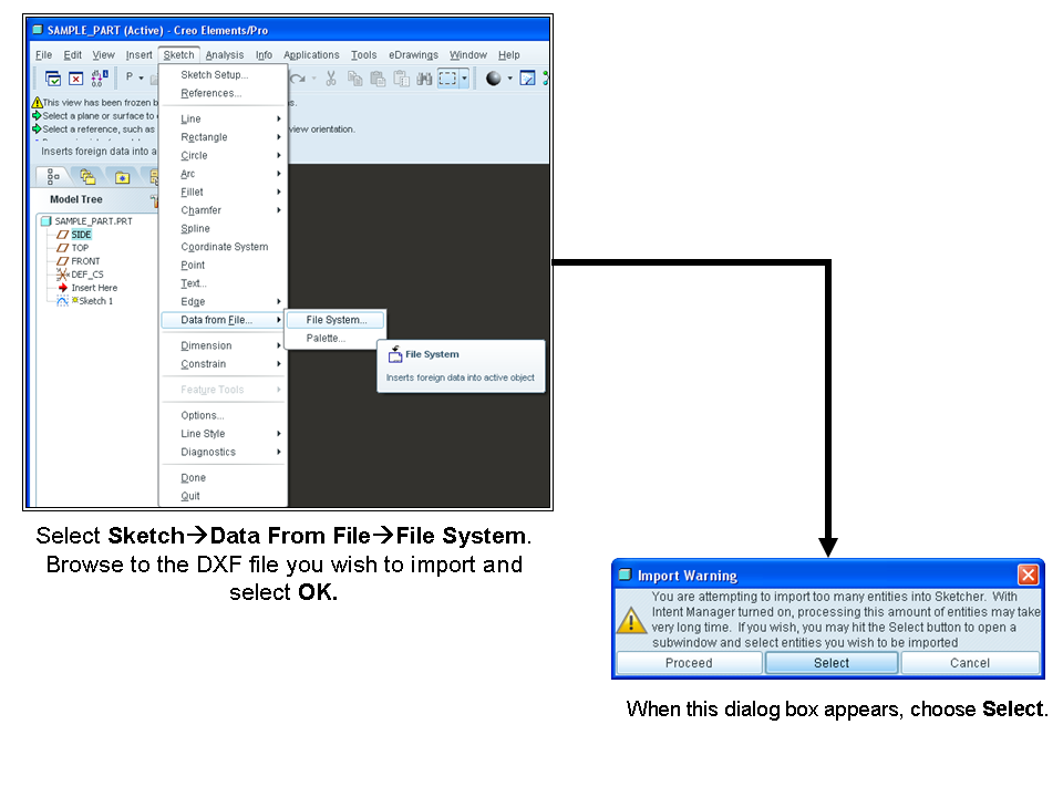
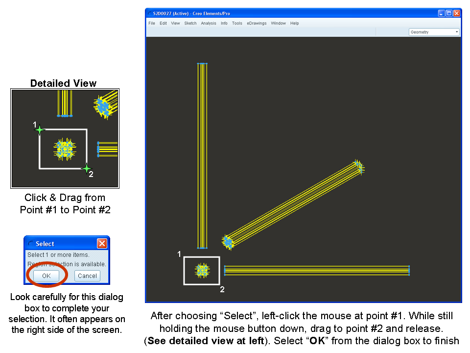
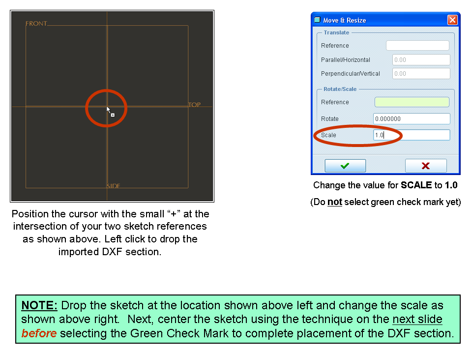
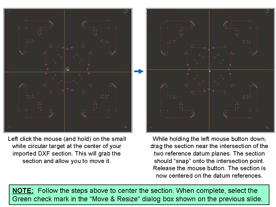
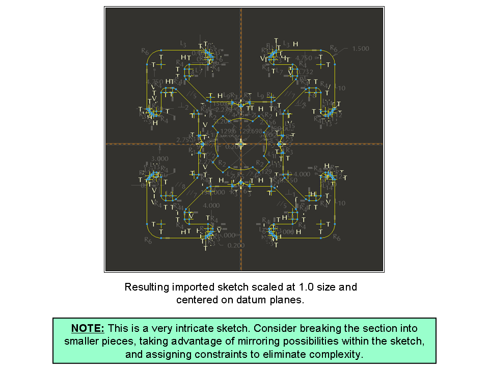
    So... I went back and checked the procedure in Creo Parametric 1.0 but it's actually the same. To elaborate on step 4, see below... click on any of the images for a larger size view that's easier to read...

    Slide1.PNG

    Slide2.PNG

    Slide3.PNG

    Slide4.PNG

    Slide5.PNG

    I hope that clears up the remainder of the steps. If this is still unclear, please let us know.

    Thanks!

    -Brian

    5 replies

    Patriot_1776
    22-Sapphire II
    December 22, 2011

    Kinda vague question. What are you going to do with this extrusion? I'd say make the imported length the generic of a family table, and make instances of the various lengths you do and might need.

    BUT, the best way to import geometry is NOT to just "Open" it, but to use your companies typical standard "start part", and do an: Insert, Data, From File. This brings in the geometry, but then you have all your layers, parameters, and default planes and CS etc. When simply opening the file, all you get is the geometry in most cases.

    24-Ruby III
    December 23, 2011

    byron freelon wrote:

    ...For example, http://www13.boschrexroth-us.com/partstream/Search.aspx ...

    Thanks for the link.

    13-Aquamarine
    December 23, 2011

    Hi Byron...

    The extrusions for this site look very, very similar to 80/20 (www.8020.net). 80/20 is nice in that you can specify a specific length of ANY protrusion in their catalog and the system will generate the file and allow you to download it. Then you can import this file (using the technique Frank outlined above) and have a perfect model in Creo.

    If you're tied to these Bosch models and the Bosch site doesn't have the same ability to generate an exact length model, I'd suggest recreating the extrusion in Creo. Simply import any extrusion the way Frank suggested, start a new sketch and copy the outline of the extrusion (utilize the "Use Edge" feature with the "Loop" option). The sketch will mimic the extrusion perfectly.

    Go back into the references editor for your sketch. In Creo Elements Pro/5 this is under Sketch>References. I'm not sure where it is in Creo 1.0. Remove all but the two datum plane references in the list. This will break the association between the imported model and your sketch. Dimensions will pop up all over the place (and it'll be messy) but the sketch will be fully and automatically dimensioned. You can tweak the dimension scheme to make more sense... or take advantage of constraints to refine the sketch further.

    The goal is to use the imported model to insure you get the correct size and shape of the extrusion. Once you're done creating a sketch representing the extrusion, you can DELETE the imported geometry. Extrude your sketch to the desired depth. The sketch should now exist standalone without the need for any references back to the import... and it should be the correct depth.

    Once you've created the extrusion once, you can always reuse the sketch for additional extrusions of the same shape. If you're using these extrusions VERY often, you might consider saving the sketches of the various extrusions into your Sketcher Palette. This will allow you to reuse those sketches quickly... and provide other designers in your company access to them, too.

    If any of this doesn't make sense, let me know and I'll demonstrate the technique for you. It sounds like more work than it really is.

    Thanks!

    -Brian

    BKF1-VisitorAuthor
    1-Visitor
    December 31, 2011

    Hi Brian,

    Can you please advise me: I can not select any aspect of the aluminum extrusion. Thus, I can not use the "Use Edge" features that you are suggesting.

    Also, I had to save the extrusion in a .prt file format. Next, from an independent instance of the creo, I opened the .prt file (which contained the extrusion). I could not follow Frank's advice because after selecting Insert, I did not see "Data"; therefore, I selected "Shared Data", the "From File". After this, I NEVER saw the file I desired to import.

    Thanks for any help,

    Byron

    13-Aquamarine
    December 31, 2011

    Hi Byron...

    Maybe I'm mistaken that you could use the edges of the imported part geometry. Perhaps you have to resketch the geometry using the import as a tracing template. I'll have to test this out and get back to you with a more comprehensive reply.

    As for Frank's suggestion, he was trying to get you an imported part with all the features of a native Creo model (standard views, datums, parameters, etc). One way to do this is by opening the import into a new Creo part. However, you no longer have to do this. There are options now to open the import directly while using your start part as a template. This has the same effect as following Frank's technique.

    Unfortunately I have to do a few minutes of further research before I can give a more complete answer. I'll have to write back in the morning. My spouse is already grumbling that I'm still answering emails at 3am... if I know what's good for me, I'd better wait until morning to fire up Creo again!

    Regards,

    -Brian

    1-Visitor
    January 3, 2012

    Hmm...I would just make a datumplane at the specified length and cut with that plane.

    It may not be that sophisticated, but it works.

    1-Visitor
    January 4, 2012

    Hi Preben

    The site does not provide full length pro-e parts

    for example a 20x20 section having full length of 3 met ; is having a length of 800mm in pro-e part provided by the site

    I dont know the required lengths of the users

    and its always good to have a parametric model

    Regards

    K.Mahanta

    1-Visitor
    January 4, 2012

    Then I would go for "Sketch" solution.

    It's fairly simple and works fine.