1-Visitor
August 1, 2016
Solved

How to solve a RC circuit, including piecewise and periodic functions in time domain?

  • August 1, 2016
  • 5 replies
  • 11040 views

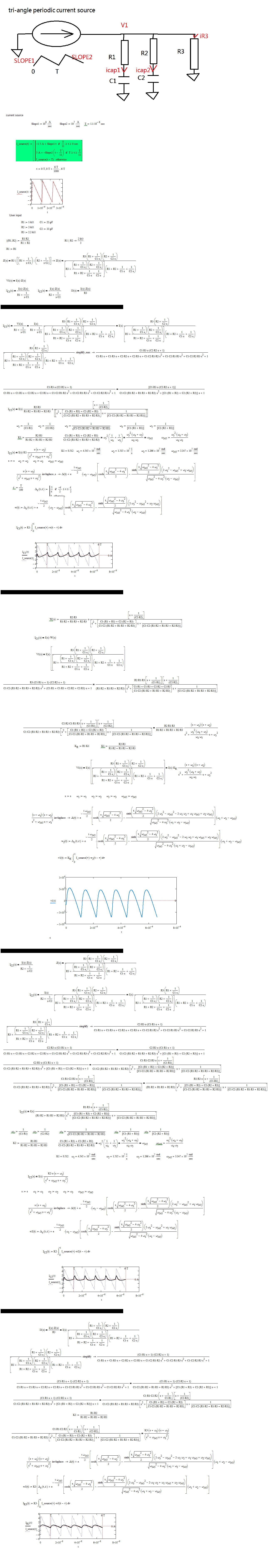
Hi All, I have a circuit like this, where I want the components value R1,C1,R2,C3 and R3 as the user inputs.

RC.jpg

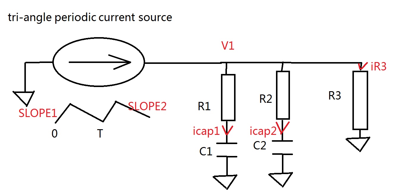
I can list the equations to solve this circuit, but I do not know how to realize it in Mathcad. Would anybody help me?

I have attached the worksheet. In addition, if this circuit can be solved, can we also add a control button, to "trigger" the Mathcad calculation by clicking it?

Thank you!

Best answer by -MFra-

I would analyze the circuit as follows (a little rushed and without comments):

circuit0.jpg

5 replies

12-Amethyst
August 1, 2016

Hi.

If you have the symbolic solution, can use this definition for Isource, which can be differentiated and integrated symbolically.

is.gif

If you want the numeric solution must to write an odesolve block with the functions that you have write, and your periodic function works for the block. But need to write in therms of the variable t, so, integration variable must to be tau or something else, and t goes at the top limit of integration: I don't understand why you put T, the period there.

About a push button to make the calculus, mathcad usually don't need that: it recalc every time that something changes in the screen area.

Best regards.

Alvaro.

yhuang-31-VisitorAuthor
1-Visitor
August 1, 2016

Hi Alvaro, thank you for your advise! I have revised my code according to your advise, but I still cannot figure out how to solve the variables symbolically. Would you directly edit from my attached file? Thank you!

12-Amethyst
August 1, 2016

Hi. Attached, the odesolve block, trying to resolve the integral equations to differentials. But can't make it to work with odesolve. Maybe another one collab can see why.

Notice also that for t=0, it's wrong to assume i1, etc equals zero. Maybe you can translate the Is to make it zero to t=0.

Symbolic solution attached to, but it's useless.

Best regards.

Alvaro.

-MFra-21-Topaz IIAnswer
21-Topaz II
August 1, 2016

I would analyze the circuit as follows (a little rushed and without comments):

circuit0.jpg

yhuang-31-VisitorAuthor
1-Visitor
August 1, 2016

Hi F.M., thank you so much for your detailed solution! I have the questions of three calculated/defined variables, would you advise?

calculation of RC circuit.JPG

(1) what is the DELTA(t) provided by inverse laplace?

(2) what is the epsilon you defined?

(3) what is the theory in defining delta_epsilon(t) to replace delta (t)?

Thank you!

21-Topaz II
August 2, 2016

Hallo yhuang-3,

the delta is the Dirac impulse. It is an impulse defined in the origin (t = 0),  of infinite amplitude and unit area. The analytical definition, approximated and simpler, is the one I provided, but there are many others. You get it to the limit, for epsilon approaching zero. The topic is covered on all texts on calculus. The Dirac delta is commonly used in physics as well as in electrical engineering. I did the approximation of the Dirac pulse, only to draw the graph. Indeed, the approximation is not necessary. Better to use the definition of the Dirac pulse, as you can see in the following image.

In laboratory practice, you have to be very attentive to the voltage and current pulses. They can destroy the user systems and measuring instruments. The classic case is the output of a differentiator when the input is a square wave signal. The output that is obtained is a train of destructive pulses.

In your problem, being the impulses integrated, there is no production of pulses.

Greetings

FM

circuit01.jpg

12-Amethyst
August 3, 2016

Attached, numerical solution. As any numeric procedure, can fail for some combination of parameters (bad-conditioned problem).

Can't get the correct Derivative vector for call rkadopt, and others, but Odesolve works, at least, for few periods.

Best regards.

Alvaro.

21-Topaz II
August 3, 2016

Hi Alvaro, I also wanted to take  "your way" very interesting, to solve the problem, but then I opted for the network inspection method. I'm doing a comparison with my results, but I find some difficulties. Could you use the unit of measure and let us have the file, please? Thank you.

FM

12-Amethyst
August 3, 2016

Hi F.M.

Can't use units with Odesolve because i is in Amperes, but I is for the integral of i along the time, then it is in A*sec. And can't mix units in the odesolve call with the vector (i1,i2,i3,I1,I2).

Best regards.

Alvaro.

yhuang-31-VisitorAuthor
1-Visitor
August 4, 2016

Hi F.M., I have another question about your solution. Would you tell me how did you express W(s) in trying to plot v(t)? I found that using laplace function, I cannot get W(S) from w(t). Thank you!

W(S).JPG

21-Topaz II
August 5, 2016

Clarification: 1) In mathcad 15 isn't necessary to approximate the Dirac's delta.

                        2) for your problem see below and the attached worksheet

Bye

FM

network0.jpg

yhuang-31-VisitorAuthor
1-Visitor
August 5, 2016

Hi F.M.,

I tried to use your initial worksheet and your latest worksheet little network.xmcd to sum I_C1,i_C2 and i_R3, and I found the sum of them do not equal to I_source(t), you can see the comparison here:

current_summation.JPG

My questions are

(1) my first priority is to plot a relatively accurate V1(t), do you think the concavity issue or anything else will impact the plot of V1(t)?

(2) I tried to use your  newly used bold L-1 symbol to calculate inverse Laplace. However, when I copied your code to my MathCAD 14, it shows like this. It is no longer bold. When I tried to use w(t):= L-1, Mathcad reports an error message that s is not defined. Do you know why it happens?

inverse laplace.JPG

Thank you!

21-Topaz II
August 8, 2016

I would like to give you some advice, concerns the circuit presented by you is really an unacceptable draft, unpresentable. You should have draw a circuit like the one here below:

little circuit0.jpg

Greetings

FM