1-Visitor
September 12, 2012
Solved

Creating Angled Hole with Counterbore

  • September 12, 2012
  • 1 reply
  • 16424 views

Hi,

First, I'm not sure if this is the correct place to post, as the community is "Creo" and I am running WF 3. However, I cannot find the WF 3 community, so if this is not the place, please point me in the right direction.

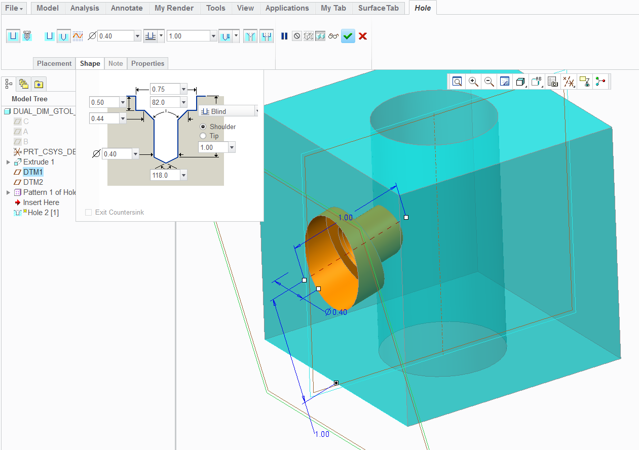
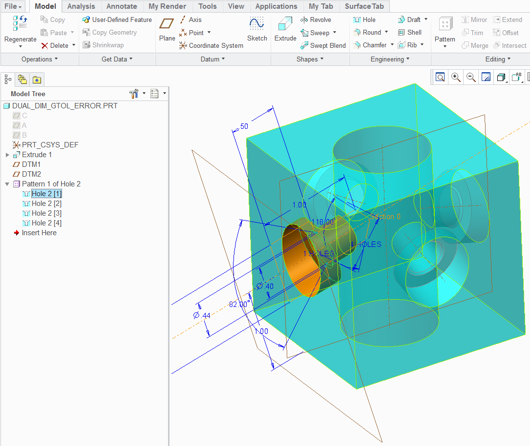
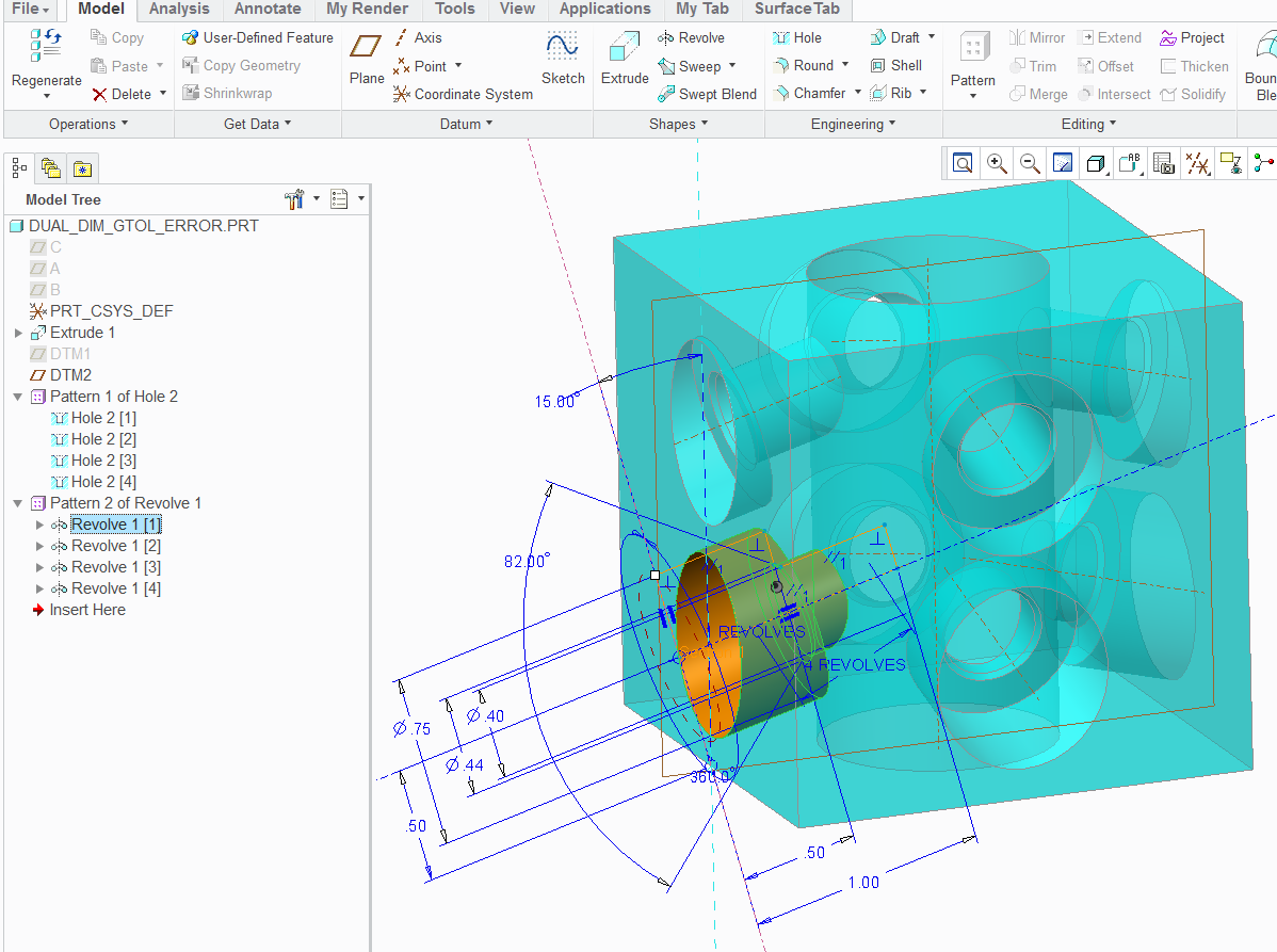
Anyway, I am trying to create a hole at an angle to a surface. The hole is also to be counter bored. I am having great difficulty doing this - I have been able to create a hole by creating an extra axis & datum plane, but it is a simple hole. When I try to change the type of hole from "simple" to "standard" (which is the only place the Counterbore option exists), it does not work (the counterbore is never on the proper surface).

Attached is a 2D sketch of what I am trying to do.

Any help would be appreciated.


This thread is inactive and closed by the PTC Community Management Team. If you would like to provide a reply and re-open this thread, please notify the moderator and reference the thread. You may also use "Start a topic" button to ask a new question. Please be sure to include what version of the PTC product you are using so another community member knowledgeable about your version may be able to assist.
Best answer by TomD.inPDX

Sometimes pictures are much better. They work great here in PlanetPTC... when they work

So this is pretty much what you did in WF3 - It is a counterbored hole feature attached to a datum plane. I did not define an axis for location.

Hole_in_Creo2.PNG

From there, I used the center axis to pattern the holes -

Hole_in_Creo2_patterned.PNG

Now this is the same hole as a revolve... and no "placement plane" -

Revolve_in_Creo2_patterned.PNG

...and it patterns the very same way as the hole did.

Pictures are nice, huh

1 reply

17-Peridot
September 12, 2012

These are much easier to define as revolve features.

Think about how the hole has to think about the depth of the counterbore. It needs a perpendicular face to define it.

Technically, I would agree that the depth could be a point in the center where the axis intersects the surface but that is not how holes are defined in WF.

This forum is fine for WF3 users too

1-Visitor
September 12, 2012

Antonius,

Thank you for your reply. However, if I have a bunch of holes to do, w/ varying diameters & counter bores, are you suggesting that I create revolve features for each of these? That seems very tedius to me, not to mention the fact that, shouldn't that be what the "hole" feature is for?

How would I create the revolved feature? Would I create it on a plane that is normal to the surface I'm wanting to cut the hole into? This seems confusing to me.

Anyway, after I posted my original question, I think I *sort* of was able to figure it out. It's not the most elegant solution, and due to the issues cited below, I'm not sure if it will work for my application.

Attached are 2 screenshots of my Pro/E model in wireframe mode. The first attachment shows how I got the (simple) hole at the angle I want. Even this seems tedious to me - so Pro/E forces me to create a whole new axis, and a whole new plane - just to create ONE simple hole??

Why can't I just pick the surface I want the hole to be in, locate it from the surfaces where I want it, then have an option to drill normal to that surface, or to drill at "X degree" angle to that surface? <-------Possible feature request!!!!

Anyway, the 2nd attachment shows the hole after I converted it to a "standard" hole (the only way I could get the Counter Bore functionality to show up). Now, one thing I'm not sure about is - does Pro/E still think there are threads in this hole (I'd like it to be a non-threaded THRU hole). Also, it is forcing me to choose a drill & thread size (ie, 10-24), which I do NOT want.

This is why I don't think this will work for me, as I do NOT want to be forced to use a UNC/UNF/ISO standard drill sized hole. Why doesn't Pro/E allow me to create a SIMPLE (ie, non-threaded) hole w/ a counter bore? Surely I am not the only person who has ever needed to do this? The hole is to be used to insert a liner bushing, then insert a slip-renewable bushing inside the liner bushing - this is not something which I would consider atypical.

Finally, as I was typing this, I thought of yet another option. Keep my original simple hole. Then create another hole w/ a larger diameter which is coaxial to the 1st hole. I could specify the depth I want the 2nd hole to go to (hence, "faking" a counterbore).

Please tell me that this is easier in Creo?? Please!!

Thanks,

Rob

Pro-E_Angled_Hole_SS.pngPro-E_Angled_Hole_CB.png

Message was edited by: Robert Brookover

17-Peridot
September 12, 2012

True, you have found the "normal" surface by defining the datum plane. However, creating the axis was optional although you do need features to be able to locate the hole in relation to the part, so the axis serves a useful purpose.

I am not 100% at WF3... I may not even be 15% as I only used it for about 3 months. But in Creo, the thread, vs non-thread, and special applications are a lot simpler. But as far as locating it, not really. You still need that "perpendicular surface" feature.

A hole in any of the Creo apps, Pro/E, WF, or Creo is still a revolve feature. It works with a planer sketch, is revolves about a primary (dedicated) centerline which becomes an axis. By calling it a hole, it simply does a lot of things behind the scenes. One of those things is the ability to tie a "cosmetic thread" feature to the hole. And these are simply defined by tables that have some presets in them for making some "curve" features that "represent" a thread and provides some smarts for detailing them in drawings.

So this will come around on you as you say that making the hole feature is easier than making lots of revolves; yet each hole still needs a normal plane for location. In the revolve, you could have left out the datum plane and used reference geometry to define the angle... and this method is very -not- unlike simply creating a hole from an -internal- sketch where you can make any size and shape hole you please; except that a hole created with a sketch -still- requires the normal "surface' to place the hole.

So the root of your question is, how do I make this easy on myself, and this is where I get lost due to my lack of WF3 knowledge. I use to use Pro/E 2000i for years and am now using Creo 2.0. Patterns in this case, yours and mine, are your friend. I know patterns are very powerful and have become more-so in the later releases. One of the most powerful additions to patterns is the ability to now pattern based on an axis. I don't know if WF3 has this yet. Regardless, it is patterning that will make your choice on how you want to make the holes work for you.

I have more often than not been thwarted by angular holes just like these. I do often opt for the simple "revolve" method. When I have several holes that I cannot pattern easily, or when the pattern functionality simply fails me over and over again... I just save the sketch and when I create the next hole, simply open the section file and use it for the second hole. Later I will create the relations to make all the whole follow the original instance.

So the tool is powerful enough, but the way of thinking is still the same as original Pro/E. Depending on what you are trying to achieve, it may even be useful to an actual planer surface for the holes and later trim the surface instead. Again, it is about planning your "history" based model. If you challenged the body of this forum with the most efficient way to achieve what you want to achieve, you will likely get a different answer, and perspective from each user. My latest find in Creo 2.0?... Creating a pattern using a sketch with datum points! It rocks

Are you planning an upgrade to Creo 2.0 anytime soon?